RESEARCH | August 22, 2017

Exploiting Industrial Collaborative Robots

Traditional industrial robots are boring. Typically, they are autonomous or operate with limited guidance and execute repetitive, programmed tasks in manufacturing and production settings.1 They are often used to perform duties that are dangerous or unsuitable for workers; therefore, they operate in isolation from humans and other valuable machinery.

This is not the case with the latest generation collaborative robots (“cobots”) though. They function with co-workers in shared workspaces while respecting safety standards. This generation of robots works hand-in-hand with humans, assisting them, rather than just performing automated, isolated operations. Cobots can learn movements, “see” through HD cameras, or “hear” through microphones to contribute to business success.

UR5 by Universal Robots2
Baxter by Rethink Robotics3

So cobots present a much more interesting attack surface than traditional industrial robots. But are cobots only limited to industrial applications? NO, they can also be integrated into other settings!

 
The Moley Robotic Kitchen (2xUR10 Arms)4
DARPA’s ALIAS Robot (UR3 Arm)5
Last February, Cesar Cerrudo (@cesarcer) and I published a non-technical paper “Hacking Robots Before Skynet” previewing our research on several home, business, and industrial robots from multiple well-known vendors. We discovered nearly 50 critical security issues. Within the cobot sector, we audited leading robots, including Baxter/Sawyer from Rethink Robotics and UR by Universal Robots.
      Baxter/Sawyer: We found authentication issues, insecure transport in their protocols, default deployment problems, susceptibility to physical attacks, and the usage of ROS, a research framework known to be vulnerable to multiple issues. The major problems we reported appear to have been patched by the company in February 2017.
     UR: We found authentication issues in many of the control protocols, susceptibility to physical attacks, memory corruption vulnerabilities, and insecure communication transport. All of the issues remain unpatched in the latest version (3.4.2.65, May 2017).6

In accordance with IOActive’s responsible disclosure policy we contacted the vendors last January, so they have had ample time to address the vulnerabilities and inform their customers. Our goal is to make cobots more secure and prevent vulnerabilities from being exploited by attackers to cause serious harm to industries, employees, and their surroundings. I truly hope this blog entry moves the collaborative industry forward so we can safely enjoy this and future generations of robots.

In this post, I will discuss how an attacker can chain multiple vulnerabilities in a leading cobot (UR3, UR5, UR10 – Universal Robots) to remotely modify safety settings, violating applicable safety laws and, consequently, causing physical harm to the robot’s surroundings by moving it arbitrarily.

This attack serves as an example of how dangerous these systems can be if they are hacked. Manipulating safety limits and disabling emergency buttons could directly threaten human life. Imagine what could happen if an attack targeted an array of 64 cobots as is found in a Chinese industrial corporation.7

The final exploit abuses six vulnerabilities to change safety limits and disable safety planes and emergency buttons/sensors remotely over the network. The cobot arm swings wildly about, wreaking havoc. This video demonstrates the attack: https://www.youtube.com/watch?v=cNVZF7ZhE-8

Q: Can these robots really harm a person?
A: Yes, a study8 by the Control and Robotics Laboratory at the École de technologie supérieure (ÉTS) in Montreal (Canada) clearly shows that even the smaller UR5 model is powerful enough to seriously harm a person. While running at slow speeds, their force is more than sufficient to cause a skull fracture.9Q: Wait…don’t they have safety features that prevent them from harming nearby humans?
A: Yes, but they can be hacked remotely, and I will show you how in the next technical section.Q: Where are these deployed?
A: All over the world, in multiple production environments every day.10Integrators Define All Safety Settings

Universal Robots is the manufacturer of UR robots. The company that installs UR robots in a specific application is the integrator. Only an integrated and installed robot is considered a complete machine. The integrators of UR robots are responsible for ensuring that any significant hazard in the entire robot system is eliminated. This includes, but is not limited to:11

  • Conducting a risk assessment of the entire system. In many countries this is required by law
  • Interfacing other machines and additional safety devices if deemed appropriate by the risk assessment
  • Setting up the appropriate safety settings in the Polyscope software (control panel)
  • Ensuring that the user will not modify any safety measures by using a “safety password.
  • Validating that the entire system is designed and installed correctly

Universal Robots has recognized potentially significant hazards, which must be considered by the integrator, for example:

  • Penetration of skin by sharp edges and sharp points on tools or tool connectors
  • Penetration of skin by sharp edges and sharp points on obstacles near the robot track
  • Bruising due to stroke from the robot
  • Sprain or bone fracture due to strokes between a heavy payload and a hard surface
  • Mistakes due to unauthorized changes to the safety configuration parameters

Some safety-related features are purposely designed for cobot applications. These features are particularly relevant when addressing specific areas in the risk assessment conducted by the integrator, including:

  • Force and power limiting: Used to reduce clamping forces and pressures exerted by the robot in the direction of movement in case of collisions between the robot and operator.
  • Momentum limiting: Used to reduce high-transient energy and impact forces in case of collisions between robot and operator by reducing the speed of the robot.
  • Tool orientation limiting: Used to reduce the risk associated with specific areas and features of the tool and work-piece (e.g., to avoid sharp edges to be pointed towards the operator).
  • Speed limitation: Used to ensure the robot arm operates a low speed.
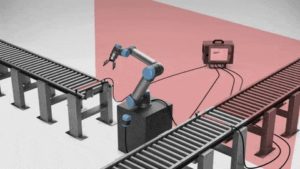
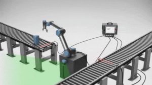
  • Safety boundaries: Used to restrict the workspace of the robot by forcing it to stay on the correct side of defined virtual planes and not pass through them.

Safety planes in action12


Safety I/O: When this input safety function is triggered (via emergency buttons, sensors, etc.), a low signal is sent to the inputs and causes the safety system to transition to “reduced” mode.

Safety scanner13
Safety settings are effective in preventing many potential incidents. But what could happen if malicious actors targeted these measures in order to threaten human life?
Statement from the UR User Guide

Changing Safety Configurations Remotely

“The safety configuration settings shall only be changed in compliance with the risk assessment conducted by the integrator.14 If any safety parameter is changed the complete robot system shall be considered new, meaning that the overall safety approval process, including risk assessment, shall be updated accordingly.”
 

The exploitation process to remotely change the safety configuration is as follows:

Step 1.    Confirm the remote version by exploiting an authentication issue on the UR Dashboard Server.
Step 2.    Exploit a stack-based buffer overflow in UR Modbus TCP service, and execute commands as root.
Step 3.    Modify the safety.conf file. This file overrides all safety general limits, joints limits, boundaries, and safety I/O values.
Step 4.    Force a collision in the checksum calculation, and upload the new file. We need to fake this number since integrators are likely to write a note with the current checksum value on the hardware, as this is a common best practice.
Step 5.    Restart the robot so the safety configurations are updated by the new file. This should be done silently.
Step 6.    Move the robot in an arbitrary, dangerous manner by exploiting an authentication issue on the UR control service.

By analyzing and reverse engineering the firmware image ursys-CB3.1-3.3.4-310.img, I was able to understand the robot’s entry points and the services that allow other machines on the network to interact with the operating system. For this demo I used the URSim simulator provided by the vendor with the real core binary from the robot image. I was able to create modified versions of this binary to run partially on a standard Linux machine, even though it was clearer to use the simulator for this example exploit.

Different network services are exposed in the URControl core binary, and most of the proprietary protocols do not implement strong authentication mechanisms. For example, any user on the network can issue a command to one of these services and obtain the remote version of the running process (Step 1):


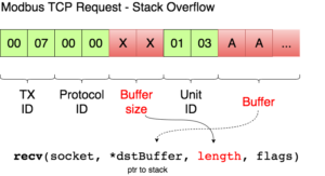
Now that I have verified the remote target is running a vulnerable image, ursys-CB3.1-3.3.4-310 (UR3, UR5 or UR10), I exploit a network service to compromise the robot (Step 2).The UR Modbus TCP service (port 502) does not provide authentication of the source of a command; therefore, an adversary could corrupt the robot in a state that negatively affects the process being controlled. An attacker with IP connectivity to the robot can issue Modbus read/write requests and partially change the state of the robot or send requests to actuators to change the state of the joints being controlled.It was not possible to change any safety settings by sending Modbus write requests; however, a stack-based buffer overflow was found in the UR Modbus TCP receiver (inside the URControl core binary).A stack buffer overflows with the recv function, because it uses a user-controlled buffer size to determine how many bytes from the socket will be copied there. This is a very common issue.

Before proceeding with the exploit, let’s review the exploit mitigations in place. The robot’s Linux kernel is configured to randomize (randomize_va_space=1 => ASLR) the positions of the stack, virtual dynamic shared object page, and shared memory regions. Moreover, this core binary does not allow any of its segments to be both writable and executable due to the “No eXecute” (NX) bit.

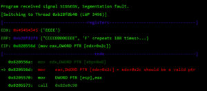
While overflowing the destination buffer, we also overflow pointers to the function’s arguments. Before the function returns, these arguments are used in other function calls, so we have to provide these calls with a valid value/structure. Otherwise, we will never reach the end of the function and be able to control the execution flow.
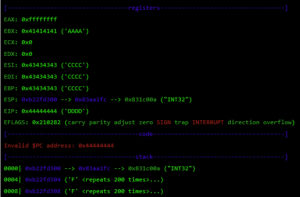
edx+0x2c is dereferenced and used as an argument for the call to 0x82e0c90. The problem appears afterwards when EBX (which is calculated from our previous controlled pointer on EDX) needs to also point to a structure where a file descriptor is obtained and is closed with “close” afterwards.

To choose a static address that might comply with these two requirements, I used the following static region, since all others change due to ASLR.

I wrote some scripts to find a suitable memory address and found 0x83aa1fc to be perfect since it suits both conditions:
      0x83aa1fc+0x2c points to valid memory -> 0x831c00a (“INT32”)
      0x83aa1fc+0x1014 contains 0 (nearly all this region is zeroed)
Now that I have met both conditions, execution can continue to the end of this function, and I get EIP control because the saved register on the stack was overflowed:


At this point, I control most of the registers, so I need to place my shellcode somewhere and redirect the execution flow there. For this, I used returned-oriented programming (ROP), the challenge will be to find enough gadgets to set everything I need for clean and reliable exploitation. Automatic ROP-chain tools did not work well for this binary, so I did it manually.First, I focus on my ultimate goal: to execute a reverse shell that connects to my machine. One key point when building a remote ROP-based exploit in Linux are system calls.Depending on the quality of gadgets that useint instructions I find, I will be able to use primitives such as write or dup2 to reuse the socket that was already created to return a shell or other post-exploitation strategies.In this binary, I only found one int 0x80 instruction. This is used to invoke system calls in Linux on x86. Because this is a one-shot gadget, I can only perform a single system call: I will use the execve system call to execute a program. This int 0x80 instruction requires setting up a register with the system call number (EAX in this case 0xb) and then set a register (EBX) that points to a special structure.This structure contains an array of pointers, each of which points to the arguments of the command to be executed.Because of how this vulnerability is triggered, I cannot use null bytes (0x00) on the request buffer. This is a problem because we need to send commands and arguments and also create an array of pointers that end with a null byte. To overcome this, I send a placeholder, like chunks of 0xFF bytes, and later on I replace them with 0x00 at runtime with ROP.In pseudocode this call would be (calls a TCP Reverse Shell):
 
 
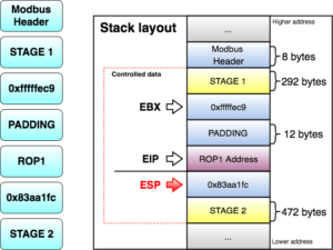
All the controlled data is in the stack, so first I will try to align the stack pointer (ESP) to my largest controlled section (STAGE 1). I divided the largest controlled sections into two stages, since they both can potentially contain many ROP gadgets. 

As seen before, at this point I control EBX and EIP. Next, I have to align ESP to any of the controlled segments so I can start doing ROP.

The following gadget (ROP1 0x8220efa) is used to adjust ESP:


This way ESP = ESP + EBX – 1 (STAGE 1 address in the stack). This aligns ESP to my STAGE 1 section. EBX should decrease ESP by 0x137 bytes, so I use the number 0xfffffec9 (4294966985) because when adding it to ESP, it wraps around to the desired value.
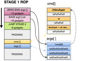
When the retn instruction of the gadget is executed, ROP gadgets at STAGE 1 start doing their magic. STAGE 1 of the exploit does the following:
  1. Zero out the at the end of the arguments structure. This way the processor will know that EXECVE arguments are only those three pointers.
  2. Save a pointer to our first command of cmd[] in our arguments structure.
  3. Jump to STAGE 2, because I don’t have much space here.
 

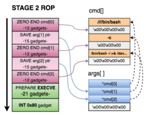
STAGE 2 of the exploit does the following:

  1. Zero out the xffxffxffxff at the end of each argument in cmd[].
  2. Save a pointer to the 2nd and 3rd argument of cmd[] in on our arguments structure.
  3. Prepare registers for EXECVE. As seen before, we needed
    1. EBX=*args[]
    2. EDX = 0
    3. EAX=0xb
  4. Call the int 0x80 gadget and execute the reverse shell.
Once the TCP reverse shell payload is executed, a connection is made back to my computer. Now I can execute commands and use sudo to execute commands as root in the robot controller.
 
Safety settings are saved in the safety.conf file (Step 3). Universal Robots implemented a CRC (STM-32) algorithm to provide integrity to this file and save the calculated checksum on disk. This algorithm does not provide any real integrity to the settings, as it is possible to generate collisions or calculate new checksum values for new settings overriding special files on the filesystem. I reversed how this calculation is being made for each safety setting and created an algorithm that replicates it. On the video demo, I did not fake the new CRC value to remain the same (located on top-right of the screen), even though this is possible and easy (Step 4).
 
Before modifying any safety setting on the robot, I setup a process that automatically starts a new instance of the robot controller after 25 seconds with the new settings. This will give me enough time to download, modify, and upload a new safety setting file. The following command sets up a new URControl process. I used Python since it allows me to close all current file descriptors of the running process when forking. Remember that I am forking from the reverse shell object, so I need to create a new process that does not inherit any of the file descriptors so they are closed when the parent URControl process dies (in order to restart and apply new safety settings).
 
 
Now I have 25 seconds to download the current file, modify it, calculate new CRC, reupload it, and kill the running URControl process (which has an older safety settings config). I can programmatically use the kill command to target the current URControl instance (Step 5).
 

Finally, I send this command to the URControl service in order to load the new installation we uploaded. I also close any popup that might appear on the UI.

 
Finally, an attacker can simply call the movej function in the URControl service to move joints remotely, with a custom speed and acceleration (Step 6). This is shown at the end of the video.

Once again, I see novel and expensive technology which is vulnerable and exploitable. A very technical bug, like a buffer overflow in one of the protocols, exposed the integrity of the entire robot system to remote attacks. We reported the complete flow of vulnerabilities to the vendors back in January, and they have yet to be patched.
What are we waiting for?
 
1 https://www.robots.com/faq/show/what-is-an-industrial-robot
2 https://www.roboticsbusinessreview.com/manufacturing/cobot-market-boom-lifts-universal-robots-fortunes-2016/
3 http://www.rethinkrobotics.com/blog/humans-and-collaborative-robots-working-together-in-grand-rapids-mi/ 
https://www.youtube.com/watch?v=G6_LCwu7dOg
4https://www.wired.com/2016/11/darpa-alias-autonomous-aircraft-aurora-sikorsky/
5 https://www.universal-robots.com/how-tos-and-faqs/faq/ur-faq/release-note-software-version-34xx/
6https://www.youtube.com/watch?v=PtncirKiBXQ&t=1s
7http://coro.etsmtl.ca/blog/?p=299
8 http://www.forensicmed.co.uk/pathology/head-injury/skull-fracture/
9https://www.universal-robots.com/case-stories/
11 https://academy.universal-robots.com
12https://academy.universal-robots.com
13Software_Manual_en_US.pdf – Universal Robots

Safety planes in action12


Safety I/O: When this input safety function is triggered (via emergency buttons, sensors, etc.), a low signal is sent to the inputs and causes the safety system to transition to “reduced” mode.

Safety Scanner 13

Safety settings are effective in preventing many potential incidents. But what could happen if malicious actors targeted these measures in order to threaten human life?

Statement from the UR User Guide

Changing Safety Configurations Remotely

“The safety configuration settings shall only be changed in compliance with the risk assessment conducted by the integrator.14 If any safety parameter is changed the complete robot system shall be considered new, meaning that the overall safety approval process, including risk assessment, shall be updated accordingly.”
 

The exploitation process to remotely change the safety configuration is as follows:

Step 1.    Confirm the remote version by exploiting an authentication issue on the UR Dashboard Server.
Step 2.    Exploit a stack-based buffer overflow in UR Modbus TCP service, and execute commands as root.
Step 3.    Modify the safety.conf file. This file overrides all safety general limits, joints limits, boundaries, and safety I/O values.
Step 4.    Force a collision in the checksum calculation, and upload the new file. We need to fake this number since integrators are likely to write a note with the current checksum value on the hardware, as this is a common best practice.
Step 5.    Restart the robot so the safety configurations are updated by the new file. This should be done silently.
Step 6.    Move the robot in an arbitrary, dangerous manner by exploiting an authentication issue on the UR control service.

By analyzing and reverse engineering the firmware image ursys-CB3.1-3.3.4-310.img, I was able to understand the robot’s entry points and the services that allow other machines on the network to interact with the operating system. For this demo I used the URSim simulator provided by the vendor with the real core binary from the robot image. I was able to create modified versions of this binary to run partially on a standard Linux machine, even though it was clearer to use the simulator for this example exploit.

Different network services are exposed in the URControl core binary, and most of the proprietary protocols do not implement strong authentication mechanisms. For example, any user on the network can issue a command to one of these services and obtain the remote version of the running process (Step 1):


Now that I have verified the remote target is running a vulnerable image, ursys-CB3.1-3.3.4-310 (UR3, UR5 or UR10), I exploit a network service to compromise the robot (Step 2).The UR Modbus TCP service (port 502) does not provide authentication of the source of a command; therefore, an adversary could corrupt the robot in a state that negatively affects the process being controlled. An attacker with IP connectivity to the robot can issue Modbus read/write requests and partially change the state of the robot or send requests to actuators to change the state of the joints being controlled.It was not possible to change any safety settings by sending Modbus write requests; however, a stack-based buffer overflow was found in the UR Modbus TCP receiver (inside the URControl core binary).A stack buffer overflows with the recv function, because it uses a user-controlled buffer size to determine how many bytes from the socket will be copied there. This is a very common issue.

Before proceeding with the exploit, let’s review the exploit mitigations in place. The robot’s Linux kernel is configured to randomize (randomize_va_space=1 => ASLR) the positions of the stack, virtual dynamic shared object page, and shared memory regions. Moreover, this core binary does not allow any of its segments to be both writable and executable due to the “No eXecute” (NX) bit.

While overflowing the destination buffer, we also overflow pointers to the function’s arguments. Before the function returns, these arguments are used in other function calls, so we have to provide these calls with a valid value/structure. Otherwise, we will never reach the end of the function and be able to control the execution flow.

edx+0x2c is dereferenced and used as an argument for the call to 0x82e0c90. The problem appears afterwards when EBX (which is calculated from our previous controlled pointer on EDX) needs to also point to a structure where a file descriptor is obtained and is closed with “close” afterwards.

To choose a static address that might comply with these two requirements, I used the following static region, since all others change due to ASLR.

I wrote some scripts to find a suitable memory address and found 0x83aa1fc to be perfect since it suits both conditions:
      0x83aa1fc+0x2c points to valid memory -> 0x831c00a (“INT32”)
      0x83aa1fc+0x1014 contains 0 (nearly all this region is zeroed)
Now that I have met both conditions, execution can continue to the end of this function, and I get EIP control because the saved register on the stack was overflowed:

At this point, I control most of the registers, so I need to place my shellcode somewhere and redirect the execution flow there. For this, I used returned-oriented programming (ROP), the challenge will be to find enough gadgets to set everything I need for clean and reliable exploitation. Automatic ROP-chain tools did not work well for this binary, so I did it manually.
 
First, I focus on my ultimate goal: to execute a reverse shell that connects to my machine. One key point when building a remote ROP-based exploit in Linux are system calls. Depending on the quality of gadgets that use int instructions I find, I will be able to use primitives such as write or dup2 to reuse the socket that was already created to return a shell or other post-exploitation strategies.

In this binary, I only found one int 0x80 instruction. This is used to invoke system calls in Linux on x86. Because this is a one-shot gadget, I can only perform a single system call: I will use the execve system call to execute a program. This int 0x80 instruction requires setting up a register with the system call number (EAX in this case 0xb) and then set a register (EBX) that points to a special structure. This structure contains an array of pointers, each of which points to the arguments of the command to be executed.
 
Because of how this vulnerability is triggered, I cannot use null bytes (0x00) on the request buffer. This is a problem because we need to send commands and arguments and also create an array of pointers that end with a null byte. To overcome this, I send a placeholder, like chunks of 0xFF bytes, and later on I replace them with 0x00 at runtime with ROP.
 
In pseudocode this call would be (calls a TCP Reverse Shell):
 
 
All the controlled data is in the stack, so first I will try to align the stack pointer (ESP) to my largest controlled section (STAGE 1). I divided the largest controlled sections into two stages, since they both can potentially contain many ROP gadgets. 

As seen before, at this point I control EBX and EIP. Next, I have to align ESP to any of the controlled segments so I can start doing ROP.
The following gadget (ROP1 0x8220efa) is used to adjust ESP:
 
 
This way ESP = ESP + EBX – 1 (STAGE 1 address in the stack). This aligns ESP to my STAGE 1 section. EBX should decrease ESP by 0x137 bytes, so I use the number 0xfffffec9 (4294966985) because when adding it to ESP, it wraps around to the desired value.
When the retn instruction of the gadget is executed, ROP gadgets at STAGE 1 start doing their magic. STAGE 1 of the exploit does the following:
  1. Zero out the at the end of the arguments structure. This way the processor will know that EXECVE arguments are only those three pointers.
  2. Save a pointer to our first command of cmd[] in our arguments structure.
  3. Jump to STAGE 2, because I don’t have much space here.
 

STAGE 2 of the exploit does the following:

  1. Zero out the xffxffxffxff at the end of each argument in cmd[].
  2. Save a pointer to the 2nd and 3rd argument of cmd[] in on our arguments structure.
  3. Prepare registers for EXECVE. As seen before, we needed
    1. EBX=*args[]
    2. EDX = 0
    3. EAX=0xb
  4. Call the int 0x80 gadget and execute the reverse shell.
Once the TCP reverse shell payload is executed, a connection is made back to my computer. Now I can execute commands and use sudo to execute commands as root in the robot controller.
 
Safety settings are saved in the safety.conf file (Step 3). Universal Robots implemented a CRC (STM-32) algorithm to provide integrity to this file and save the calculated checksum on disk. This algorithm does not provide any real integrity to the settings, as it is possible to generate collisions or calculate new checksum values for new settings overriding special files on the filesystem. I reversed how this calculation is being made for each safety setting and created an algorithm that replicates it. On the video demo, I did not fake the new CRC value to remain the same (located on top-right of the screen), even though this is possible and easy (Step 4).
 
Before modifying any safety setting on the robot, I setup a process that automatically starts a new instance of the robot controller after 25 seconds with the new settings. This will give me enough time to download, modify, and upload a new safety setting file. The following command sets up a new URControl process. I used Python since it allows me to close all current file descriptors of the running process when forking. Remember that I am forking from the reverse shell object, so I need to create a new process that does not inherit any of the file descriptors so they are closed when the parent URControl process dies (in order to restart and apply new safety settings).
 
 
Now I have 25 seconds to download the current file, modify it, calculate new CRC, reupload it, and kill the running URControl process (which has an older safety settings config). I can programmatically use the kill command to target the current URControl instance (Step 5).
 

Finally, I send this command to the URControl service in order to load the new installation we uploaded. I also close any popup that might appear on the UI.


Finally, an attacker can simply call the movej function in the URControl service to move joints remotely, with a custom speed and acceleration (Step 6). This is shown at the end of the video.

Once again, I see novel and expensive technology which is vulnerable and exploitable. A very technical bug, like a buffer overflow in one of the protocols, exposed the integrity of the entire robot system to remote attacks. We reported the complete flow of vulnerabilities to the vendors back in January, and they have yet to be patched.

What are we waiting for?

 
1 https://www.robots.com/faq/show/what-is-an-industrial-robot
2 https://www.roboticsbusinessreview.com/manufacturing/cobot-market-boom-lifts-universal-robots-fortunes-2016/
3 http://www.rethinkrobotics.com/blog/humans-and-collaborative-robots-working-together-in-grand-rapids-mi/ 
https://www.youtube.com/watch?v=G6_LCwu7dOg
4https://www.wired.com/2016/11/darpa-alias-autonomous-aircraft-aurora-sikorsky/
5 https://www.universal-robots.com/how-tos-and-faqs/faq/ur-faq/release-note-software-version-34xx/
6https://www.youtube.com/watch?v=PtncirKiBXQ&t=1s
7http://coro.etsmtl.ca/blog/?p=299
8 http://www.forensicmed.co.uk/pathology/head-injury/skull-fracture/
9https://www.universal-robots.com/case-stories/
11 https://academy.universal-robots.com
12https://academy.universal-robots.com
13Software_Manual_en_US.pdf – Universal Robots
RESEARCH | March 1, 2017

Hacking Robots Before Skynet

Robots are going mainstream in both private and public sectors – on military missions, performing surgery, building skyscrapers, assisting customers at stores, as healthcare attendants, as business assistants, and interacting closely with our families in a myriad of ways. Robots are already showing up in many of these roles today, and in the coming years they will become an ever more prominent part of our home and business lives. But similar to other new technologies, recent IOActive research has found robotic technologies to be highly insecure in a variety of ways that could pose serious threats to the people and organizations they operate in and around.
 
This blog post is intended to provide a brief overview of the full paper we’ve published based on this research, in which we discovered critical cybersecurity issues in several robots from multiple vendors. The goal is to make robots more secure and prevent vulnerabilities from being used maliciously by attackers to cause serious harm to businesses, consumers, and their surroundings. The paper contains more information about the research, findings, and cites many sources used in compiling the information presented in the paper and this post.
 
Robot Adoption and Cybersecurity
Robots are already showing up in thousands of homes and businesses. As many of these “smart” machines are self-propelled, it is important that they’re secure, well protected, and not easy to hack. If not, instead of helpful resources they could quickly become dangerous tools capable of wreaking havoc and causing substantive harm to their surroundings and the humans they’re designed to serve.
 
We’re already experiencing some of the consequences of substantial cybersecurity problems with Internet of Things (IoT) devices that are impacting the Internet, companies and commerce, and individual consumers alike. Cybersecurity problems in robots could have a much greater impact. When you think of robots as computers with arms, legs, or wheels, they become kinetic IoT devices that, if hacked, can pose new serious threats we have never encountered before.
 
With this in mind, we decided to attempt to hack some of the more popular home, business, and industrial robots currently available on the market. Our goal was to assess the cybersecurity of current robots and determine potential consequences of possible cyberattacks. Our results show how insecure and susceptible current robot technology is to cyberattacks, confirming our initial suspicions.
 
Cybersecurity Problems in Today’s Robots
We used our expertise in hacking computers and embedded devices to build a foundation of practical cyberattacks against robot ecosystems. A robot ecosystem is usually composed of the physical robot, an operating system, firmware, software, mobile/remote control applications, vendor Internet services, cloud services, networks, etc. The full ecosystem presents a huge attack surface with numerous options for cyberattacks.
 
We applied risk assessment and threat modeling tools to robot ecosystems to support our research efforts, allowing us to prioritize the critical and high cybersecurity risks for the robots we tested. We focused on assessing the most accessible components of robot ecosystems, such as mobile applications, operating systems, firmware images, and software. Although we didn’t have all the physical robots, it didn’t impact our research results. We had access to the core components, which provide most of the functionality for the robots; we could say these components “bring them to life.”
 
Our research covered home, business, and industrial robots, as well as the control software used by several other robots. The specific robot vendors evaluated in the research are identified in the published research paper.
 
We found nearly 50 cybersecurity vulnerabilities in the robot ecosystem components, many of which were common problems. While this may seem like a substantial number, it’s important to note that our testing was not even a deep, extensive security audit, as that would have taken a much larger investment of time and resources. The goal for this work was to gain a high level sense of how insecure today’s robots are, which we accomplished. We will continue researching this space and go deeper in future projects.
 
An explanation of each main cybersecurity issue discovered is available in the published research paper, but the following is a high-level (non-technical) list of what we found:
·         Insecure Communications
·         Authentication Issues
·         Missing Authorization
·         Weak Cryptography
·         Privacy Issues
·         Weak Default Configuration
·         Vulnerable Open Source Robot Frameworks and Libraries
 
We observed a broad problem in the robotics community: researchers and enthusiasts use the same – or very similar – tools, software, and design practices worldwide. For example, it is common for robots born as research projects to become commercial products with no additional cybersecurity protections; the security posture of the final product remains the same as the research or prototype robot. This practice results in poor cybersecurity defenses, since research and prototype robots are often designed and built with few or no protections. This lack of cybersecurity in commercial robots was clearly evident in our research.
 
Cyberattacks on Robots

Our research uncovered both critical- and high-risk cybersecurity problems in many robot features. Some of them could be directly abused, and others introduced severe threats. Examples of some of the common robot features identified in the research as possible attack threats are as follows:

  • Microphones and Cameras
  • External Services Interaction
  • Remote Control Applications
  • Modular Extensibility
  • Network Advertisement
  • Connection Ports
A full list with descriptions for each is available in the published paper.
 
New technologies are typically prone to security problems, as vendors prioritize time-to-market over security testing. We have seen vendors struggling with a growing number of cybersecurity issues in multiple industries where products are growing more connected, including notably IoT and automotive in recent years. This is usually the result of not considering cybersecurity at the beginning of the product lifecycle; fixing vulnerabilities becomes more complex and expensive after a product is released.
 
The full paper provides an overview of the many implications of insecure robots as they become more prominent in home, business, industry, healthcare, and other applications. We’ve also included many recommendations in the paper for ways to design and build robotic technology more securely based on our findings.
 
Click here for more information on the research and to view the full paper for additional details and descriptions.   
INSIGHTS | March 22, 2016

Inside the IOActive Silicon Lab: Interpreting Images

In the post “Reading CMOS layout,” we discussed understanding CMOS layout in order to reverse-engineer photographs of a circuit to a transistor-level schematic. This was all well and good, but I glossed over an important (and often overlooked) part of the process: using the photos to observe and understand the circuit’s actual geometry.


Optical Microscopy

Let’s start with brightfield optical microscope imagery. (Darkfield microscopy is rarely used for semiconductor work.) Although reading lower metal layers on modern deep-submicron processes does usually require electron microscopy, optical microscopes still have their place in the reverse engineer’s toolbox. They are much easier to set up and run quickly, have a wider field of view at low magnifications, need less sophisticated sample preparation, and provide real-time full-color imagery. An optical microscope can also see through glass insulators, allowing inspection of some underlying structures without needing to deprocess the device.
 
This can be both a blessing and a curse. If you can see underlying structures in upper-layer images, it can be much easier to align views of different layers. But it can also be much harder to tell what you’re actually looking at! Luckily, another effect comes to the rescue – depth of field.


Depth of field

When using an objective with 40x power or higher, a typical optical microscope has a useful focal plane of less than 1 µm. This means that it is critical to keep the sample stage extremely flat – a slope of only 100 nm per mm (0.005 degrees) can result in one side of a 10x10mm die being in razor-sharp focus while the other side is blurred beyond recognition.
 
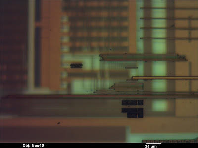
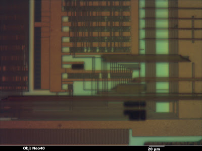
In the image below (from a Micrel KSZ9021RN gigabit Ethernet PHY) the top layer is in sharp focus but all of the features below are blurred—the deeper the layer, the less easy it is to see.
We as reverse engineers can use this to our advantage. By sweeping the focus up or down, we can get a qualitative feel for which wires are above, below, or on the same layer as other wires. Although it can be useful in still photos, the effect is most intuitively understood when looking through the eyepiece and adjusting the focus knob by hand. Compare the previous image to this one, with the focal plane shifted to one of the lower metal layers.
I also find that it’s sometimes beneficial to image a multi-layer IC using a higher magnification than strictly necessary, in order to deliberately limit the depth of field and blur out other wiring layers. This can provide a cleaner, more easily understood image, even if the additional resolution isn’t necessary.


Color

Another important piece of information the optical microscope provides is color.  The color of a feature under an optical microscope is typically dependent on three factors:
  •       Material color
  •        Orientation of the surface relative to incident light
  •        Thickness of the glass/transparent material over it

 
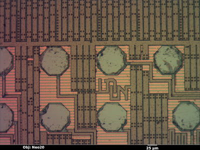
Material color is the easiest to understand. A flat, smooth surface of a substance with nothing on top will have the same color as the bulk material. The octagonal bond pads in the image below (a Xilinx XC3S50A FPGA), for example, are made of bare aluminum and show up as a smooth silvery color, just as one would expect. Unfortunately, most materials used in integrated circuits are either silvery (silicon, polysilicon, aluminum, tungsten) or clear (silicon dioxide or nitride). Copper is the lone exception.
 
Orientation is another factor to consider. If a feature is tilted relative to the incident light, it will be less brightly lit. The dark squares in the image below are vias in the upper metal layer which go down to the next layer; the “sag” in the top layer is not filled in this process so the resulting slopes show up as darker. This makes topography visible on an otherwise featureless surface.
The third property affecting observed color of a feature is the glass thickness above it. When light hits a reflective surface under a transparent, reflective surface, some of the beam bounces off the lower surface and some bounces off the top of the glass. The two beams interfere with each other, producing constructive and destructive interference at wavelengths equal to multiples of the glass thickness.
 
This is the same effect responsible for the colors seen in a film of oil floating on a puddle of water–the reflections from the oil’s surface and the oil-water interface interfere. Since the oil film is not exactly the same thickness across the entire puddle, the observed colors vary slightly. In the image above, the clear silicon nitride passivation is uniform in thickness, so the top layer wiring (aluminum, mostly for power distribution) shows up as a uniform tannish color. The next layer down has more glass over it and shows up as a slightly different pink color.
 
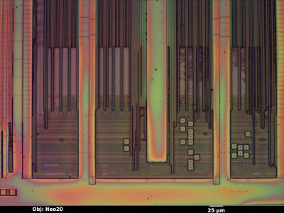
Compare that to the image below (an Altera EPM3064A CPLD). The thickness of the top passivation layer varies significantly across the die surface, resulting in rainbow-colored fringes.
 

Electron Microscopy

The scanning electron microscope is the preferred tool for imaging finer pitch features (below about 250 nm). Due to the smaller wavelength of electron beams as compared to visible light, this tool can obtain significantly higher resolutions.
 
The basic operating principle of a SEM is similar to an old-fashioned CRT display: electromagnets move a beam of electrons in a vacuum chamber in a raster-scan pattern over the sample. At each pixel, the beam interacts with the sample, producing several forms of radiation that the microscope can detect and use for imaging.
 
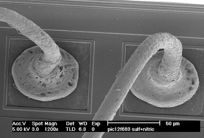
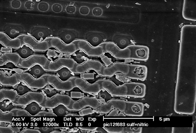
Electron microscopy in general has an extremely high depth of field, making it very useful for imaging 3D structures. The image below (copper bond wires on a Microchip PIC12F683) has about the same field of view as the optical images from the beginning of this article, but even from a tilted perspective the entire loop of wire is in sharp focus.


Secondary Electron Images

The most common general-purpose image detector for the SEM is the secondary electron detector. When a high-energy electron from the scanning beam grazes an atom in the sample, it sometimes dislodges an electron from the outer shell. Secondary electrons have very low energy, and will slow to a stop after traveling a fairly short distance. As a result, only those generated very near the surface of the sample will escape and be detected.
 
This makes secondary electron images very sensitive to topography. Outside edges, tilted surfaces, and small point features (dust and particulates) show up brighter than a flat surface because a high percentage of the secondary electrons are generated near exposed surfaces of the specimen. Inward-facing edges show up dimmer than a flat surface because a high percentage of the secondary electrons are absorbed in the material.
 
The general appearance of a secondary electron image is similar to a surface lit up with a floodlight. The eye position is that of the objective lens, and the “light source” appears to come from the position of the secondary electron detector.
 
In the image below (the polysilicon layer of a Microchip PIC12F683 before cleaning), the polysilicon word lines running horizontally across the memory array have bright edges, which shows that they are raised above the background. The diamond-shaped source/drain areas have dark “shadowed” edges, showing that they are lower than their surroundings (and thus many of the secondary electrons are being absorbed). The dust particles and loose tungsten via plugs scattered around the image show up very brightly because they have so much exposed surface area.
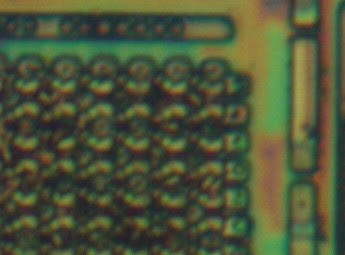
Compare the above SEM view to the optical image of the same area below. Note that the SEM image has much higher resolution, but the optical image reveals (through color changes) thickness variations in the glass layer that are not obvious in the SEM. This can be very helpful when trying to gauge progress or uniformity of an etch/polish operation.
In addition to the primary contrast mechanism discussed above, the efficiency of secondary electron emission is weakly dependent on the elemental composition of the material being observed. For example, at 20 kV the number of secondary electrons produced for a given beam current is about four times higher for tungsten than for silicon (see this paper). While this may lead to some visible contrast in a secondary electron image, if elemental information is desired, it would be preferable to use a less topography-sensitive imaging mode.
 

Backscattered Electron Images

Secondary electron imaging does not work well on flat specimens, such as a die that has been polished to remove upper metal layers or a cross section. Although it’s often possible to etch such a sample to produce topography for imaging in secondary electron mode, it’s usually easier to image the flat sample using backscatter mode.
 
When a high-energy beam electron directly impacts the nucleus of an atom in the sample, it will bounce back at high speed in the approximate direction it came from. The probability of such a “backscatter” event happening depends on the atomic number Z of the material being imaged. Since backscatters are very energetic, the surrounding material does not easily absorb them. As a result, the appearance of the resulting image is not significantly influenced by topography and contrast is primarily dependent on material (Z-contrast).
 
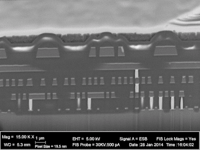
In the image below (cross section of a Xilinx XC2C32A CPLD), the silicon substrate (bottom, Z=14) shows up as a medium gray. The silicon dioxide insulator between the wires is darker due to the lower average atomic number (Z=8 for oxygen). The aluminum wires (Z=13) are about the same color as the silicon, but the titanium barrier layer (Z=22) above and below is significantly brighter. The tungsten vias (Z=74) are extremely bright white. Looking at the bottom right where the via plugs touch the silicon, a thin layer of cobalt (Z=27) silicide is visible.

Depending on the device you are analyzing, any or all of these three imaging techniques may be useful. Knowledge of the pros and cons of these techniques and the ability to interpret their results are key skills for the semiconductor reverse engineer.
INSIGHTS | June 11, 2013

Tools of the Trade – Incident Response, Part 1: Log Analysis

There was a time when I imagined I was James Bond zip lining into a compromised environment, equipped with all kinds of top-secret tools. I would wave my hands over the boxes needing investigation, use my forensics glasses to extract all malware samples, and beam them over to Miss Moneypenny (or “Q” for APT concerns) for analysis. I would produce the report from my top-notch armpit laser printer in minutes. I was a hero.
As wonderful as it sounds, this doesn’t ever happen in real life. Instead of sporting a classy tuxedo, we are usually knee deep in data… often without boots! I have recently given a few presentations(1) on Incident Response (IR). The question I am most often asked concerns the tool chain that would enable an individual or a team to perform the basic actions one would expect from an Incident Responder.

Let me be clear. There is an immense difference between walking on to a crime scene in which your organization’s intent is to bring a perpetrator to court and approximately 90% of the actual IR work you will perform. The biggest difference has to do with how you collect and handle evidence, and you can rest assured that any improperly handled evidence will be relentlessly attacked by the defense.
However, I am writing this blog post from the point of view of a blue team member. I’ll focus on the tools that are available to determine what has happened, when it happened, and (most importantly) how to make sure it does not happen again.
TL;DR : Many, if not all, of the tools you will need are available in the SANS   Investigate Forensics Toolkit (SIFT) VMWare image(2) . You can skip the rest of this post and start playing with these tools right away if you want to, but I hope I can at least give you some pointers on where to look first.
As I illustrated in the introduction, IR work is incredibly unsexy. Almost without exception, you will run into a special case that requires you to work on the command line for hours trying to figure out what has occurred. The next-next finish of many a security product installation and use process is something you will nostalgically reflect on over a burning log (pun intended).
You will typically have in your possession three important pieces of evidence:
  • Log files
  • Memory images
  • Disk images
I will address these in three separate blog posts and try to give you some ideas about the tools you can use during your investigation.
In this blog post, we will start off by looking at log files.
Every device on the network creates a gigantic amount of data. Some of it is used for monitoring purposes, but most of it is (hopefully) stored and never to be looked at again. Until a system is compromised, this data is generally useless with the exception of a few hidden golden threads. These threads will give you a good starting point for figuring out what has happened. They might also be useful in tying the whole story together.  Essentially, you must figure out what the log files want to tell you. (Cue the X-Files soundtrack.)
Sifting through log files is like looking for gold. Your initial sift will be very coarse grained. As you get rid of more and more of the dirt, the mesh of your sift will get finer and finer.
In my humble opinion, there is nothing better than having a thorough understanding of the Unix command-line tools ‘grep’, ‘sed’, and ‘awk’.  The good thing about these tools is that you will find them on almost any Unix or Linux box you can get your hands on. The bad thing is that you will either need to know or need to find out what you are looking for.
In the absence of a full-fledged SIEM infrastructure, two tools exist that I recommend you become familiar with:
  • OSSEC(3)
  • log2timeline(6)
First up, OSSEC. Not only is this a good (and open-source) host-based intrusion detection system, but it also allows you to feed it collected logs through its command-line tools!  The events will trigger OSSEC out-of-the-box alerts and give you a good overview of the most interesting events that have taken place. You can also easily develop custom rule sets based on (as an example) publicly available data from other compromises(4)
As you become more experienced with OSSEC, you can build your own set of scripts, drawing inspiration from a variety of places. In cases where ye olde *nix is not available, make sure you are also familiar with a Windows shell tool. (Powershell is one heck of an alternative!) Also, keep your Command Line Kung Fu(5) handy!
You will not be able to perform IR without the powerful yet extremely elegant log2timeline(6) tool. This blog post does not offer enough space to provide a decent overview of log2timeline. In essence, it groks data from different sources and creates a ‘Super Timeline’ that helps you to narrow in on those timeframes that are relevant to your investigation. It is one thing to dig through information on a command line, but it is a completely different ball game when you can visualize events as they have occurred.
In upcoming blog posts, I will dig into the juicy secrets that can be found in memory and disk images. A major lesson to be learned as you climb on the ladder of IR is that many of the tools you will use are produced by your peers. Sure, IR software is available and works well. However, the bulk of tools available to you have been developed by your fellow incident responders to address a particular problem. Many responders generously release their tools to the public domain for others to use. We learn from others probably more than we teach.
 

(1) BYO-IR: Build Your Own Incident Response: http://www.slideshare.net/wremes/isc2-byo-ir
(2) http://computer-forensics.sans.org/community/downloads
(3) http://www.ossec.net
(4) e.g. APT1 Indicators of Compromise @ http://intelreport.mandiant.com/
(5) http://blog.commandlinekungfu.com/
(6) http://log2timeline.net/

INSIGHTS | March 25, 2013

SQL Injection in the Wild

As attack vectors go, very few are as significant as obtaining the ability to insert bespoke code in to an application and have it automatically execute upon “inaccessible” backend systems. In the Web application arena, SQL Injection vulnerabilities are often the scariest threat that developers and system administrators come face to face with (albeit way too regularly).  In fact the OWASP Top-10 list of Web threats lists SQL Injection in first place.

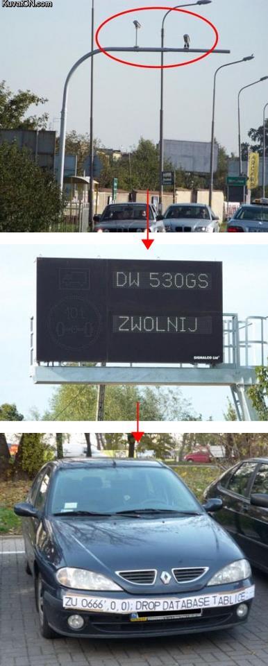
More often than not, when security professionals discuss SQL Injection threats and attack vectors, they focus upon the Web application context. So it was with a bit of fun last week when I came across a photo of a slightly unorthodox SQL Injection attempt – that of someone attempting to subvert a traffic monitoring system by crafting a rather novel vehicle license plate.

My original tweet got retweeted a couple of thousand of times – which just goes to show how many security nerds there are out there in the twitterverse.

“in the wild” SQL Injection attempt was based upon the premise that video cameras are actively monitoring traffic on a road, reading license plates, and issuing driver warnings, tickets or fines as deemed appropriate by local law enforcement.
At some point the video captures of the passing vehicle’s license plate must be converted to text and stored – almost certainly in some kind of backend database. The hope of the hacker that devised this attack was that the process would be vulnerable to SQL Injection – and crafted a simple SQL statement that could potentially cause the backend database to drop (i.e. “delete”) the table containing all of the license plate information.
Whether or not this particular attempt worked, I have no idea (probably not if I have to guess an outcome); but it does help nicely to raise attention to this category of vulnerability.
As surveillance systems become more capable – digitally storing information, distilling meta-data from image captures, and sharing observation data between systems – it opens many new doors for mischievous and malicious attack.
The physical nature of these systems, coupled with the complexities of integration with legacy monitoring and reporting systems, often makes them open to attacks that would be classed as fairly simple in the world of Web application security.
A common failure of system developers is to assume that the physical constraints of the data acquisition process are less flexible than they are. For example, if you’re developing a traffic monitoring system it’s easy to assume that license plates are a fixed size and shape, and can only contain 10 alphanumeric characters. Meanwhile, the developers of the third-party image processing code had no such assumptions and will digitize any image. It reminds me a little of the story in which reuse of some object-oriented code a decade ago resulted in Kangaroos firing Stinger missiles during a military training simulation.
While the image above is amusing, I’ve encountered similar problems before when physical tracking systems integrate with digital backend processes – opening the door to embarrassing and fraudulent events. For example, in the past I’ve encountered similar SQL Injection vulnerabilities within systems such as:
  • Toll booths reading RFID tags mounted on vehicle windshields – where the tag readers would accept up to 2k of data from each tag (even though the system was only expecting a 16 digit number).
  • Credit card readers that would accept pre-paid cards with negative balances – which resulted in the backend database crediting the wrong accounts.
  • RFID inventory tracking systems – where a specially crafted RFID token could automatically remove all record of the previous hours’ worth of inventory logging information from the database allowing criminals to “disappear” with entire truckloads of goods.
  • Luggage barcode scanners within an airport – where specially crafted barcodes placed upon the baggage would be automatically conferred the status of “manually checked by security personnel” within the backend tracking database.
  • Shipping container RFID inventory trackers – where SQL statements could be embedded to adjust fields within the backend database to alter Custom and Excise tracking information.


Unlike the process of hunting for SQL Injection vulnerabilities within Internet accessible Web applications, you can’t just point an automated vulnerability scanner at the application and have at it. Assessing the security of complex physical monitoring systems is generally not a trivial task and requires some innovative approaches. Experience goes a long way.
— Gunter Ollmann, CTO IOActive Inc.