
Several weeks ago, international regulators announced that they were ordering Boeing 787 operators to completely shut down the plane’s electrical power whenever it had been running for 51 days without interruption.1 The FAA published an airworthiness directive elaborating on the issue, and I was curious to see what kind of details were in this document.
While I eventually discovered that there wasn’t much information in the FAA directive, there was just enough to put me on track to search for the root cause of the issue. This blog post will leverage the interesting bits of information in the FAA directive to gain knowledge about some avionics concepts.
First, we need to introduce the parts of the 787’s architecture and systems that are relevant to this issue. The FAA directive explicitly uses acronyms, such as CDN or CCS, that need to be defined before moving to root cause analysis.
What is the Common Core System (CCS)?
As opposed to the federated avionics architectures, which make use of distributed avionics functions that are packaged as self-contained units, Integrated Modular Avionics (IMA)2 architectures employ a high-integrity, partitioned environment that hosts multiple avionics functions of different criticalities on a shared computing platform. Boeing engineers went one step further and developed the Common Core System (CCS) for the 787, a further enhancement based on an open IMA avionics technology.
Essentially the CCS is a hardware/software platform that provides computing, communication, and input-output (I/O) services for implementing real-time embedded systems, known as hosted functions.
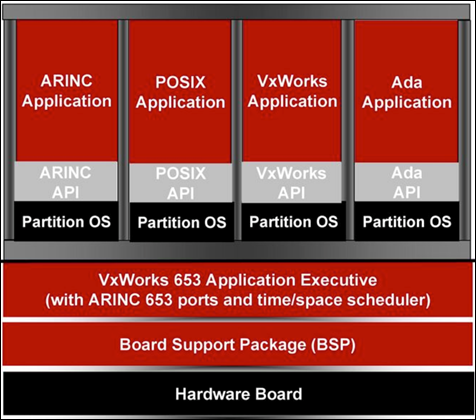
Multiple hosted functions share the platform resources within a virtual system environment enforced by partitioning mechanisms that are implemented as part of the platform design, relying on a VxWorks 6533,4 OS.5
This virtual system partitioning environment guarantees that hosted functions are isolated from each other, so it supports highly critical applications but also lower levels of application integrity. Remember that international regulations define five levels of failure conditions, categorized by their effects on the aircraft, crew, and passengers:
Level A–Catastrophic
Failure may cause multiple fatalities, usually with loss of the airplane.
Level B–Hazardous
Failure has a large negative impact on safety or performance, reduces the ability of the crew to operate the aircraft due to physical distress or a higher workload, or causes serious or fatal injuries among the passengers.
Level C–Major
Failure significantly reduces the safety margin or significantly increases crew workload. May result in passenger discomfort (or even minor injuries).
Level D–Minor
Failure slightly reduces the safety margin or slightly increases crew workload. Examples might include causing passenger inconvenience or a routine flight plan change.
Level E–No Effect
Failure has no impact on safety, aircraft operation, or crew workload.
Software approved to levels A, B, or C requires strong certification involving formal processes for verification and traceability
As a result, a DO-178B6 Level-A software may coexist in the same physical shared resource with a Level-E application.
Ideally, the applications cannot interfere with each
other, regardless of faults that may occur within the hosted functions or the
platform resources, which are predetermined and communicated to the platform
components via loadable configuration files usually in either XML or
proprietary binary formats.
Within the CCS we can find the following major components:
- General Processing Modules (GPMs) to support functional processing needs
- Remote Data Concentrators (RDCs) to support system analog signals, analog discrete signals, and serial digital interfaces (CAN bus8, A4299, etc.)
- Avionics Full Duplex (A664-P7) Switched Ethernet10 network for communication between platform elements
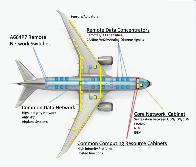
These elements can be packaged as Line Replaceable Units (LRUs)11 or in module or card form, which can then be grouped within cabinets or integrated LRUs. As a result, the CCS is made up of:
- Two (2) Common Computing Resource (CCR) cabinets
- The Common Data Network (CDN)
- 21 RDCs
Common Computing Resource Cabinets
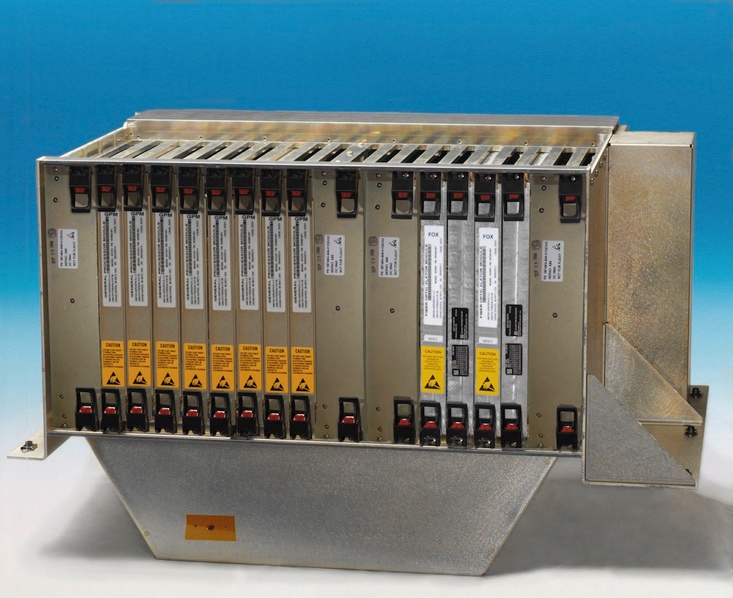
Each CCR cabinet has:
- Two (2) Power Conditioning Modules (PCMs)
- Eight (8) General Processing Modules (GPMs)
- Two (2) ARINC 664-P7 network Cabinet Switches
(ACSs) - Two (2) Fiber Optic Translator Modules (FOXs)
- Two (2) Graphic Generators (part of the Display
and Alert Crew System)
Each GPM is an independent computing platform that hosts airplane systems’ operational software and provides the hosted applications a partitioned environment based on the ARINC 653 standard. Each GPM has the same hardware and core operating system.
The GPMs in these CCR cabinets run hosted functions such as Remote Power Distribution System (RPDS), Generator/Bus Power Control Unit (GCU/BPCU),13 Circuit Breaker Indication and Control, Landing Gear Indication and Control, Thrust Management Function, and Flight Management Function.
Common Data Network
The CDN is a high-integrity IEEE 802.3 Ethernet network utilizing IP addressing and related transport protocols (UDP). As an A664-P7 compliant network, it also implements deterministic timing and redundancy management protocols. The CDN uses both fiber optic cable and copper wire and moves system information between the various airplane systems connected to it, either directly or through ACSs, FOXs, or RDCs.
The CDN is comprised of the network End System (ES) hosted in each connecting end node and multiple network switches.
End System
Within the context of an avionics network, as defined in the A664-P7 specification, we find that:
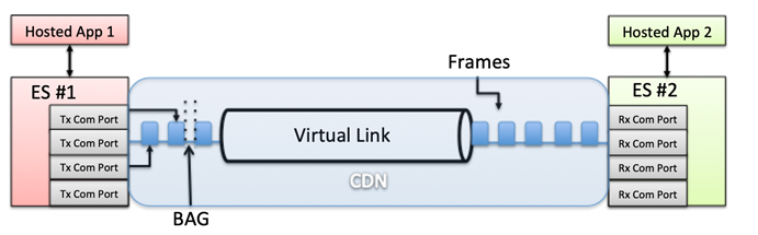
The main function of the End System (ES) is to provide services, which guarantee a secure and reliable data exchange to the partition software.
Essentially, the ES is assuming the role of a Network Interface Controller (NIC), capable of maintaining communication ports (queuing, sampling, or SAP) for messages written and read by multiple hosted applications. This is performed by exchanging Ethernet frames through a Virtual Link (VL), which is a conceptual communication object that defines a logical unidirectional connection from one source to one or more destination ES. The traffic flow in the VL is shaped not to exceed a configured Bandwidth Allocation Gap (BAG), which represents the minimum time interval between the first bits of two consecutive frames.
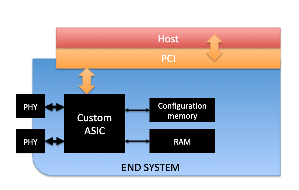
The ES operating in the CDN (also in the switches) is physically separated from the host processor, interfacing through a PCI Bus. From a high-level perspective, it is comprised of:
- One (1) custom ASIC
- Two (2) COTS Ethernet PHY transceivers
- Two (2) serial configuration memories
- RAM
The ES can be configured from the host through a proprietary API. This configuration data has been previously generated using a DO-178B Level-A tool (ESBIN) and then stored in a custom file (es_config.bin).
The ES in a CDN switch implements much the same functionality except for some addressing and redundancy operations.
Remote Data Concentrators
There are 21 RDCs in the CCS.
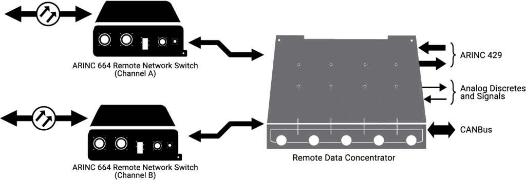
These RDCs provide the interface between airplane systems that do not have the ability to support A664-P7 in the CDN.
The RDCs convert these signals to ARINC 664 data and vice versa, thus effectively acting as a gateway for a variety of analog devices, such as sensors or valves, ARINC 429 buses, and CAN subnets.
From an A664-P7 perspective, these RDCs map:
- Analog signals to parameters
- A429 to communication ports
- CAN bus to both parameters and communication
ports
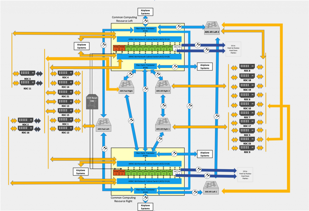
As a result, the high-level architecture would be as follows.
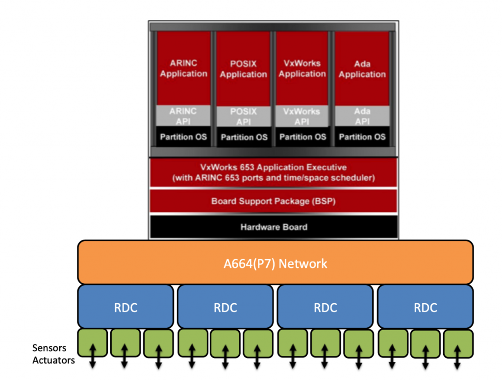
To better illustrate this architecture as a whole, we can oversimplify one of the hosted functions to see how all the pieces work together.
The landing gear control software is running in one of the CCRs, hosted in a GPM’s partition. This hosted function partition receives gear lever up/down data as well as gear and gear door position data from one of the 21 RDC via the CDN. Then, depending on the signals received, the landing gear control software may issue gear-sequencing commands to the proper RDC via the CDN. The RDC can then transfer the specific signal to those actuators that, for example, energize the control valves to retract and extend the landing gear or open and close the gear doors.
Root Cause Analysis
The FAA’s directive is scarce in technical details. It only contains a high-level description of the issue; however, it provides the reader with some key facts that can help with root cause analysis:
The FAA has received a report indicating that the stale-data monitoring function of CCS may be lost when continuously powered on for 51 days. This could lead to undetected or unannunciated loss of CDN message age validation, combined with a CDN switch failure. The CDN handles all the flight-critical data (including airspeed, altitude, attitude, and engine operation), and several potentially catastrophic failure scenarios can result from this situation. Potential consequences include:
- Display of misleading primary attitude data for both pilots.
- Display of misleading altitude on both pilots’ primary flight displays (PFDs).
- Display of misleading airspeed data on both pilots’ PFDs, without annunciation
- of failure, coupled with the loss of stall warning, or over-speed warning.
- Display of misleading engine operating indications on both engines.
The potential loss of the stale-data monitoring function of the CCS when continuously powered on for 51 days, if not addressed, could result in erroneous flight-critical data being routed and displayed as valid data, which could reduce the ability of the flight crew to maintain the safe flight and landing of the airplane.
I will be carefully analyzing every single sentence.
The FAA has received a report indicating that the stale-data monitoring function of CCS may be lost when continuously powered on for 51 days.
Back in 2015, the FAA issued a similar directive14 although in that case the underlying problem was described a bit more explicitly.
We have been advised by Boeing of an issue identified during laboratory testing.
The software counter internal to the generator control units (GCUs) will overflow after 248 days of continuous power.
So basically, we can probably assume the situation is pretty much the same: Boeing identified this current issue during laboratory testing.
The 2015 FAA directive also explicitly mentioned that Boeing was working on a software patch to fix the issue; however, there is no mention of any upcoming patch in this current directive. As we will see later on, this makes sense if the vulnerability is hardware-related.
Once again, the mention of “51 days” initially points towards some kind of overflow in a counter.
This could lead to undetected or unannunciated loss of CDN message age validation, combined with a CDN switch failure.
This sentence tells us a lot of things about the nature of the issue. First, any catastrophic error in the CDN that goes undetected or ‘unannunciated’ in the 787 is highly unexpected, although it’s not entirely clear to me whether both the loss of CDN message age validation and CDN switch failure go undetected or just the first issue. Both maintenance engineers and pilots have the ability to check the status of the CCS switches and CDN LRUs through the maintenance pages in the Flight Deck. Also, any significant fault will be centralized, logged, and processed via the Central Maintenance Computing Function (CMCF).
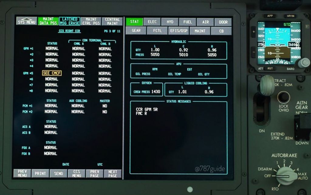
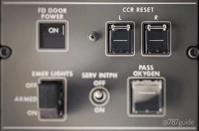
Also, pilots can reset both left and right CCR on the overhead panel; however, as the FAA directive states, a complete power shutdown is required, so we can assume a CCR reset doesn’t solve the problem. This means the issue is located deep in the hardware of a component that is present not only in the CCR, but also in other parts of the CDN.
So we have that:
- The CDN loses the ability to perform age
validation. - The CDN switches fail.
Let’s narrow down the list of potential suspects by analyzing how data communication integrity is enforced in the CDN.
Integrity Checking in the CDN
Bear in mind that the CCS is an asynchronous system where each partition is not only controlling when its data is produced but also decoupling this operation from the network interface. At the MAC level, the A664-P7 spec mandates that the output interfaces need to be transmitting, regardless of the PHY status, in order to prevent error propagation or re-transmission of old frames. Still, in an AFDX avionics network the order matters, so when the transmitting partition produces certain data, the receiver partition expects to collect that data in the same order.
In addition, the CCS operates following a redundancy policy having two different channels (‘A’ and ‘B’), although it is theoretically possible to configure them to operate independently.
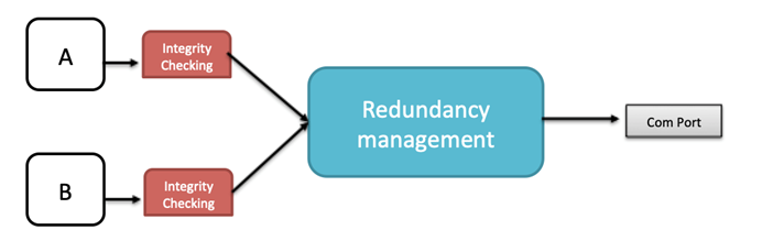
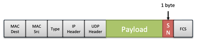
In order to fulfill these requirements, the ES adds a Sequence Number (SN) after the AFDX payload when transmitting frames. This SN is 0 right after the ES reset and then 1-255. The redundant frames received in the ES follow the ‘first valid wins’ policy. Please note that in addition to the ordinal integrity there is a procedure to detect real redundant frames, where a configured constant (Skew Max) is used to limit the valid time window for two potentially redundant frames.
This logic is common to all AFDX ES and I don’t think this functionality is where the actual flaw lies, as any problem would be more dependent on the amount of traffic flowing through the CDN rather than a specific time period. However, interestingly, there is something in the ES’ integrity checking and redundancy management that makes the 787 a little bit special: Boeing’s proprietary Error Detection Encoding (EDE) protocol.
EDE Protocol: A Promising Suspect
The EDE protocol is working at the VL level to add an additional layer of end-to-end integrity in the CDN.
When a VL is enabled with EDE, which is mandated by Boeing for critical and essential data, the transmitting ES encapsulates the payload with an EDE header and footer.
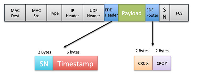
The EDE header and footer include the following fields:
- SN: A 2-byte sequence number bound to a specific
COM port. This value is incremented for each frame that is transmitted. - Timestamp: A 6-byte value that holds the time
when the message was transmitted, using the local clock domain of the
transmitting ES. - CRC X and CRC Y: These CRCs are calculated using
the EDE Source ID (a 32-bit value only known for the ES transmitter and
receiver in a VL), EDE timestamp, and payload.
The EDE timestamp is relative to the transmitting ES’ clock domain, so the CCS needs a way to centralize and keep track of all the local time references so any age validation can be performed accurately. This task is cyclically performed by the Time Management function, which maintains a table of relative offsets with the relationships between the time references for each ES present in the CDN. This is possible thanks to a request/response protocol where the Time Agent in each ES is periodically questioned by the Time Managers.
The resulting table of offsets is then broadcast to each ES through the Time Offset message so an ES can perform EDE age verification when receiving data from another ES. Obviously, the EDE Time Management packets required to calculate and propagate these offset tables are not subject to EDE age verification.
Age verification in the CDN, in the context of the EDE protocol, relies on the consistency of these offset tables. So, what would happen if, for any reason, this fails? It is difficult to say without having access to a 787 (currently accepting donations) 😉 but I will try my best.
There are several possible scenarios:
- The ES did not receive the offsets table.
The message is forwarded to the EDE Redundancy Manager but a flag is set to indicate its age cannot be validated. - The age is greater than the maximum configured age.
The message is directly discarded. - The age is less than the maximum configured age.
This is the expected case. The message is forwarded to the EDE Redundancy Manager, eventually reaching the COM port. - The age is inconsistent.
For some reason, the message seems to have an age that makes no sense. For example, let’s imagine that the timestamp set by the transmitting ES is close to its wrap-around value. After performing the required calculation, the receiving ES obtains a timestamp that has already wrapped-around, so it would look like the message had been received before it was actually sent. The message is accepted but still handled as its age is unknown.
Bearing in mind that this functionality is implemented in the ASIC and the timestamp should be derived from a counter, I think the whole issue may be around this logic.
The key question is: How does the 51-day period fit in this scenario? Ok, let me present my theory.
A Potential Explanation
The 6-byte EDE timestamp is the key to make sure everything goes smoothly in the CDN. The most significant bit in this timestamp is set 0 by definition, so ideally we have 0x7FFFFFFFFFFF as the maximum coherent value for the EDE timestamp.
The ES receives the data from the hosted application through PCI, running at 33MHz, so it would be reasonable to implement a counter at a similar clock frequency so the ASIC can use that clock reference to timestamp ready-to-go messages. So let’s assume the counter is ideally operating at 33MHz and the timestamp is somehow derived from that counter, also taking into account different parameters, such as delays and latencies due to moving data across the different interfaces (RMII, PCI, etc.).
By calculating the frequency at which an ideal counter (starting at 0) should be operating in order to wrap-around the EDE timestamp (0x800000000000) after 51 days, we obtain ~32MHz. That’s pretty close to our assumption.
The CDN handles all the flight-critical data (including airspeed, altitude, attitude, and engine operation), and several potentially catastrophic failure scenarios can result from this situation.
We previously introduced the DO-178B certification levels where level A corresponds to a catastrophic failure, which prevents continued safe flight or landing.
Potential consequences include:
- Display of misleading primary attitude data for both pilots.
- Display of misleading altitude on both pilots’ primary flight displays (PFDs).
- Display of misleading airspeed data on both pilots’ PFDs, without annunciation of failure, coupled with the loss of stall warning, or over-speed warning.
- Display of misleading engine operating indications on both engines.
The consequences covered in the FAA document seem to be strictly related to the scenario where pilots can no longer trust their instruments, a problem that in past incidents has led to tragic consequences.
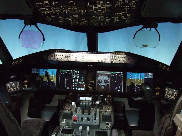
In a Boeing 787, all this data is handled by the Display Crew Alert System (DCAS). This system provides the pilots with all the audio, tactile, or visual indications that are necessary for the safe operation of the airplane, as you can see in the following image.
The potential loss of the stale-data monitoring function of the CCS when continuously powered on for 51 days, if not addressed, could result in erroneous flight-critical data being routed and displayed as valid data, which could reduce the ability of the flight crew to maintain the safe flight and landing of the airplane.
We can read this last paragraph as a summary of what has been elaborated in this blog post.
Conclusion
Aviation security research is a complicated field, not only because of the secrecy that surrounds these technologies but also the commercial and corporate barriers that prevent access to the required equipment. Despite all these challenges, I think that any effort to promote this kind of research always pays off.
The timing is also interesting, as this flaw is coming to light almost a year after reporting our research to Boeing. Boeing acknowledged that they set up a fully functional aircraft and a laboratory to assess our claims (which involved the CDN), so I guess there is a chance that, maybe, follow-up research on their part identified this issue. In general terms, this would be a good side-effect of any security research, which is all about fostering the appropriate level of trust in the devices and organizations the people depend upon.
Do not take what I have presented here as the real root cause of the problem that Boeing detected. I may be right, but it’s just as likely that I’m wrong, and this was an exercise intended to satisfy my curiosity. Hopefully, you have learned something new and enjoyed reading about the topic. The more thoughtful people there are carefully scrutinizing critical systems, the better those systems will be in the long-term. That’s what this is all about.
For additional reading, please refer to the white paper of my original research, which was released during Black Hat 2019.
[A] IOActive White Paper: Arm IDA and Cross Check: Reversing the 787’s Core Network
[1] https://www.federalregister.gov/documents/2020/03/23/2020-06092/airworthiness-directives-the-boeing-company-airplanes
[2] https://www.aviationtoday.com/2007/02/01/integrated-modular-avionics-less-is-more/
[3] https://en.wikipedia.org/wiki/ARINC_653
[4] https://www.windriver.com/products/product-overviews/vxworks-653-product-overview-multi-core/vxworks-653-product-overview-multi-core.pdf
[5] https://www.windriver.com/customers/customer-success/aerospace-defense/boeing/ (404 link broken)
[6] https://en.wikipedia.org/wiki/DO-178B
[7] http://www.artist-embedded.org/docs/Events/2007/IMA/Slides/ARTIST2_IMA_WindRiver_Wilson.pdf
[8] https://en.wikipedia.org/wiki/CAN_bus
[9] https://en.wikipedia.org/wiki/ARINC_429
[10] https://pdfs.semanticscholar.org/5db4/b539ed7bdec182448ac8d7219db12a8bbc12.pdf
[11] https://en.wikipedia.org/wiki/Line-replaceable_unit
[12] https://bioage.typepad.com/.a/6a00d8341c4fbe53ef0162fbf813b6970d
[13], [14] https://s3.amazonaws.com/public-inspection.federalregister.gov/2015-10066.pdf
[15], [16] https://www.instagram.com/787guide/