Today we are taking you one step deeper into a microchip than we usually go. We look at transistors and the logic functions they compose, which helps us understand custom ASICs now found in some secured processors.
To reverse-engineer the secret functionality of an ASIC, we identify logic blocks, map out the wiring between the blocks, and reconstruct the circuit diagram. Today, we’ll only be looking at the first step: reading logic. And we start with the easiest example of a logic function: the inverter.
To read logic, you first have to find the transistors and decide where Vcc (+) and ground (-) are located. Transistors are easy to spot. They will always look very similar to those two transistors marked in the picture: A rectangle shape with a line in the middle. Vcc is always next to the larger transistors (PMOS) and ground is closer to the smaller ones (NMOS).
Once you identified the transistors, you draw a small circuit diagram that shows how they are connected to each other. In the example, the inputs of the two transistors are connected and so are their outputs on the left side. From this circuit diagram you can read that whatever you assert at the input, the output will be forced to the opposite state — an inverter.
Every gate will follow these basic principles, but vary in the number and constellation of transistors. A 2-NOR gate (Y = !(A|B) ), for instance, is composed of 4 transistors in this setup:
Once you figured out a gate, you can recognize every occurrence of that function on the whole chip because the exact same shape is always used for the same function. Generally, you only need to read a few dozens gates at most to generate a map of functions across whole chip. Get a head start on reading logic and check out the logic gate collection at The Silicon Zoo.
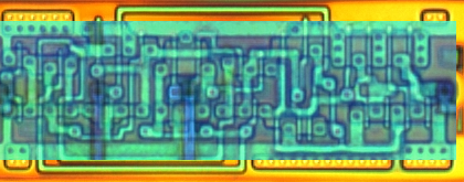
Here is a challenge for you to try (open in GIMP or Photoshop and toggle between the different layers):


