This is Part-3 of a 3-Part Series. Check out Part-1 here and Part-2 here.
This is the third in a series of three posts in which I break down the creation of a unique key fob badge for the 2024 Car Hacking Village (CHV). Part 1 is an overview of the project and the major components; I recommend that you begin there. In Part 2 I discussed some of the software aspects and the reasoning behind certain decisions.
Background
Before I discuss how to interact with the key fob using a computer, it’s probably a sensible idea to cover some basics of Passive Entry Passive Start (PEPS).
PEPS is a system that allows for keyless entry and ignition in vehicles. Here’s how it operates:
Key Fob Communication:
The key fob communicates with the car using radio-frequency (RF) signals. These signals are typically in the low-frequency (LF) range (125 kHz or 134 kHz) for car-to-key-fob communication, and in the ultra-high-frequency (UHF) range (sub-1 GHz) for key-fob-to-car.
Proximity Detection:
As the key fob approaches the car, it exchanges unique access codes with the vehicle. The car’s system measures the distance between the key fob and the vehicle. The LF communication operates in the near field, meaning the key fob must be close to the car to receive the signal. The key fob then responds using UHF, which operates in the far field, allowing it to communicate back to the car from a greater distance.
Passive Entry:
When the door handle is touched, the car verifies the key’s presence and unlocks the doors. This can be done through a triggered system, where the car scans for the key fob when the handle is touched, or a polling system, where the car continuously scans for the key fob’s presence.
Passive Start:
Once inside the vehicle, the engine can be started by pressing the ignition button. The car’s system ensures the key fob is inside the vehicle before allowing the engine to start, adding an extra layer of security.
That all makes sense, right? I always find a good sequence diagram helpful to reinforce things like this, so I made one. The process for unlock and start are fundamentally the same, so to avoid repeating myself, I will focus here on the unlock process.
As illustrated in the sequence diagram, it often starts off as either the driver touching the door handle or the driver approaching the car. For simplicity’s sake, I will again narrow the focus to the driver touching the door handle. In simple steps:

- Driver touches the door handle
- Vehicle sends a wake message to the key fob
- Key fob responds
- Vehicle sends a cryptographic challenge to the key fob
- Key fob responds with a correct cryptographic response, which is the result of the cryptographic algorithm, the challenge, and the pre-shared key.
- Vehicle unlocks.
Anyone with a software-defined radio can capture the UHF signals from the key fob to the car, but capturing the LF signals from the car to the key fob typically require special antenna and a device called an upconverter. This is not intended as a primer on RF or SDR, and if you’d like to learn more, it’s definitely worthwhile to read up on any topics like these that you may be unsure of.
As previously mentioned, the signal from the car to the key fob is LF (125/134KHz) and the key fob to the car is UHF, and interacting with UHF is trivial when using most software-defined radios. However, the LF aspect can be more challenging.
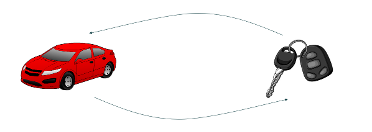
Remember, all we want to do is interact with the key fob. In Part 2 I discuss how the key fob can receive LF messages and then transmit them after some basic checks via an obfuscation algorithm. In this sequence diagram (Figure 2), you can see how the wake-up message is followed by the key fob’s acknowledgement. Any short message we send to the key fob via LF will be echoed back after obfuscation using UHF.

The question is, how can we send LF (125/134KHz) signals to the key fob from a laptop?
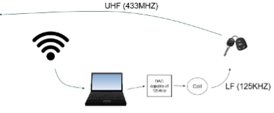
Figure 3 shows a laptop with the left side connected to an SDR and the right side connected to a Digital-to-Analog Converter (DAC), an electronic device that converts digital signals into analog signals.
Here’s a more detailed look at how it works and its applications.
Conversion Process
The input to a DAC is a digital signal, typically in the form of binary numbers (0s and 1s). The output is an analog signal, which can be a continuous voltage or current that varies smoothly over time.
A DAC takes the digital input and converts it into a corresponding analog value. For example, in audio applications, a DAC converts digital audio files into analog signals that can drive speakers to produce sound.
The conversion involves mapping the digital values to specific voltage or current levels. This process is crucial for applications where precise analog output is needed.
Applications
DACs can convert a variety of digital signals, such as:
- Audio: DACs are used in music players, smartphones, and other audio devices to convert digital audio files into analog signals that can be heard through speakers or headphones.
- Video: In televisions and video equipment, DACs convert digital video data into analog signals for display.
- Instrumentation: DACs are used in various measurement and control systems to generate precise analog signals from digital data.
There are a few key elements to focus on in the above description, besides the tasks a DAC is designed for. The interesting part for any hacker is its use for audio conversion. The LF signals our key fob is sending have quite slow data rates, meaning they actually would be audible if not for the carrier. The carrier frequency is 125 or 134KHz, so we would need a DAC capable of 250KHz+ in order to comply with the Nyquist theorem.
Among other things, the theorem states that to accurately reconstruct a continuous signal from its samples, the sampling rate must be at least twice the highest frequency present in the signal. This minimum rate is known as the Nyquist rate.
So, if our carrier frequency is 125 or 134KHz, we need at least twice that.
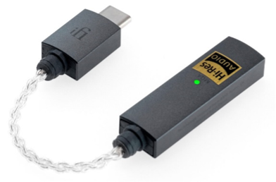
If you look to high resolution audio devices, especially DACs, you can often find a maximum conversion rate of 384KHz. This is more than twice the carrier frequency, meaning that we can use readily available high resolution audio DACs such as the device below from iFi.
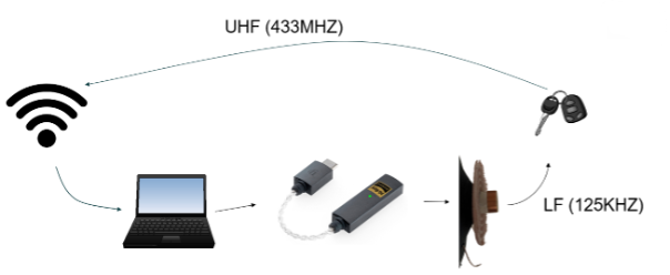
The other important aspect for conversion is the coil or antenna. Now that we have an audio device that can generate the signals we need, we need an antenna. In the sentence, “a DAC converts digital audio files into analog signals that can drive speakers to produce sound,” the word “speaker” should jump out.
If you have never dismantled a speaker, it is a relatively easy task, and the result will look something like the following image.

Now put all this together, and we have something along the lines of Figure 6:
The physical aspect is now sorted, so I will move on to the software.
I like to use GNU Radio, which is a fantastic tool and open source as well. It is a powerful signal processing tool, and once you get the hang of it, it’s relatively easy to use to build new flowgraphs – charts representing the blocks through which samples flow.
The following chart encodes a message of 0x550102030405060708, unpacks the 8 bit bytes into a bit stream, then modulates it. I have included both a Wav File Sink, for writing the data to a file for replaying later using a tool like Audacity, and an audio sink, for sending the output directly to a high-resolution audio device like the one mentioned above.
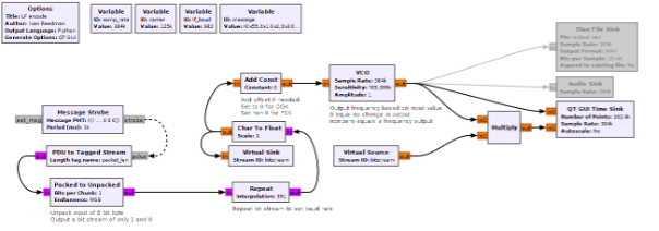
Starting on the left side, we have a message strobe which allows us to send out a message every x milliseconds. I have chosen once per second, or every 1000ms. If you follow the arrows, it should all make sense. The message strobe sends a message to the PDU to Tagged Stream block, where the message is converted into a byte stream. Next, we unpack the bytes and convert them into bits, which is ultimately what we want to send in this case.
The next section of the flow chart repeats the symbol enough times to set our data rate. In this instance we want a data rate of 982 baud, so each bit symbol needs to be repeated 391 times. I have added descriptions under each major block to help you follow along.
After converting the byte type into float (where the purple is converted to brown), the flow chart goes through a voltage controlled oscillator (VCO). A VCO is an electronic oscillator whose frequency of oscillation is controlled by an input voltage. The frequency of the output signal varies in direct proportion to the applied voltage.
However, we are not using voltage, and everything here is digital and binary, all represented by ones and zeros. If you think of a 1 as a voltage and 0 as the absence of a voltage, the VCO will output a frequency based on the sensitivity value.
Those are the basics on how we’re using GNU Radio; if you’d like to dive deeper, I’ve made the flowgraph available on the same GitHub location as the software.
Moving along, after the VCO we have a modulated bit stream that represents the original message shown in hex. You may also notice a multiply block. If the VCO receives a 0, it will not change the output, meaning whatever value it was at previously is where it will stay. This will result in a DC offset; that is, a voltage present when the input is 0. To remove this DC offset, which will ultimately upset the audio DAC and potentially the speaker coil, the multiply block takes the output from the VCO and our bit stream. If there is a 0 in our bit stream, the output of the VCO is multiplied by 0, resulting in a 0, so no DC offset. If there is a 1 in our bitstream, the VCO output is multiplied by 1, so the VCO output is maintained.
When the GNU Radio flowgraph is run, you should see something like the following:
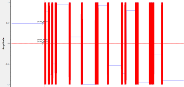
The blue signal represents the actual output of the VCO; however, it’s behind the red signal, which is the cleaned output of the VCO. They align perfectly, except for whenever the blue signal has a DC offset, as mentioned earlier.
By enabling the audio sink and connecting the audio DAC, we can now output the LF signals required to energize the LF side of the key fob.
The last piece of the puzzle is to listen to the key fob’s UHF transmissions.

A straightforward RF receiver is at work here. The quadrature (I/Q) data gets transformed into amplitude through a complex-to-magnitude block, followed by a low-pass filter. This process results in clear amplitude changes that correspond perfectly with the ones and zeros transmitted by the key fob.
For the RTLSDR Source, change Center Freq (Hz) to the value of freq. Notice how the variable freq is defined as 433.92M. The other change to make in this source really depends on the antenna you are using but for this purpose, try changing RF Gain to 48. Your particular SDR and antenna may warrant either much lower gain or higher gain.

Moving to the Low Pass Filter properties, configure Decimation along with Cutoff Freq and Transition Width.

Finally, configure the GUI Time Sink. There are lots of configuration items to change here so step through them slowly.
First the Number of Points, then Y min and Y max. The configuration values above adjust the default values used in the blocks if you were to draw this flowgraph in GNURadio. As some of the items are not visually present on the flowgraph itself, I have stepped through each of the blocks and changes to the default values that are required to make this flow graph work.

Stepping through the items on this tab change “Number of Points” to 256, “Y min” to -2 and “Y max” to 2. Then click on the Trigger tab and set the Trigger Mode and Trigger Level.

Once all of those configurations have been set, you should be ready to run the graph.
When the flow chart is run and a button is pressed on the key fob, the trace on screen should look something like the following graph, with the filtered amplitude showing distinct binary states.

You should notice the series of ones and zeros at the start. This is the preamble, as discussed previously. This is followed by two zeros indicating the end of the pre-amble.
And there you go. I could do many more posts on how to demodulate the key fob data and build Python blocks in GNU Radio to remove the obfuscation, but where would be the fun in that? I’ll instead leave that for those who are interested in having a good time.
Stay tuned for other material we will be publishing topics like this, including how-to videos on various software-defined radio techniques.

