RESEARCH | August 22, 2017

Exploiting Industrial Collaborative Robots

Traditional industrial robots are boring. Typically, they are autonomous or operate with limited guidance and execute repetitive, programmed tasks in manufacturing and production settings.1 They are often used to perform duties that are dangerous or unsuitable for workers; therefore, they operate in isolation from humans and other valuable machinery.

This is not the case with the latest generation collaborative robots (“cobots”) though. They function with co-workers in shared workspaces while respecting safety standards. This generation of robots works hand-in-hand with humans, assisting them, rather than just performing automated, isolated operations. Cobots can learn movements, “see” through HD cameras, or “hear” through microphones to contribute to business success.

UR5 by Universal Robots2
Baxter by Rethink Robotics3

So cobots present a much more interesting attack surface than traditional industrial robots. But are cobots only limited to industrial applications? NO, they can also be integrated into other settings!

 
The Moley Robotic Kitchen (2xUR10 Arms)4
DARPA’s ALIAS Robot (UR3 Arm)5
Last February, Cesar Cerrudo (@cesarcer) and I published a non-technical paper “Hacking Robots Before Skynet” previewing our research on several home, business, and industrial robots from multiple well-known vendors. We discovered nearly 50 critical security issues. Within the cobot sector, we audited leading robots, including Baxter/Sawyer from Rethink Robotics and UR by Universal Robots.
      Baxter/Sawyer: We found authentication issues, insecure transport in their protocols, default deployment problems, susceptibility to physical attacks, and the usage of ROS, a research framework known to be vulnerable to multiple issues. The major problems we reported appear to have been patched by the company in February 2017.
     UR: We found authentication issues in many of the control protocols, susceptibility to physical attacks, memory corruption vulnerabilities, and insecure communication transport. All of the issues remain unpatched in the latest version (3.4.2.65, May 2017).6

In accordance with IOActive’s responsible disclosure policy we contacted the vendors last January, so they have had ample time to address the vulnerabilities and inform their customers. Our goal is to make cobots more secure and prevent vulnerabilities from being exploited by attackers to cause serious harm to industries, employees, and their surroundings. I truly hope this blog entry moves the collaborative industry forward so we can safely enjoy this and future generations of robots.

In this post, I will discuss how an attacker can chain multiple vulnerabilities in a leading cobot (UR3, UR5, UR10 – Universal Robots) to remotely modify safety settings, violating applicable safety laws and, consequently, causing physical harm to the robot’s surroundings by moving it arbitrarily.

This attack serves as an example of how dangerous these systems can be if they are hacked. Manipulating safety limits and disabling emergency buttons could directly threaten human life. Imagine what could happen if an attack targeted an array of 64 cobots as is found in a Chinese industrial corporation.7

The final exploit abuses six vulnerabilities to change safety limits and disable safety planes and emergency buttons/sensors remotely over the network. The cobot arm swings wildly about, wreaking havoc. This video demonstrates the attack: https://www.youtube.com/watch?v=cNVZF7ZhE-8

Q: Can these robots really harm a person?
A: Yes, a study8 by the Control and Robotics Laboratory at the École de technologie supérieure (ÉTS) in Montreal (Canada) clearly shows that even the smaller UR5 model is powerful enough to seriously harm a person. While running at slow speeds, their force is more than sufficient to cause a skull fracture.9Q: Wait…don’t they have safety features that prevent them from harming nearby humans?
A: Yes, but they can be hacked remotely, and I will show you how in the next technical section.Q: Where are these deployed?
A: All over the world, in multiple production environments every day.10Integrators Define All Safety Settings

Universal Robots is the manufacturer of UR robots. The company that installs UR robots in a specific application is the integrator. Only an integrated and installed robot is considered a complete machine. The integrators of UR robots are responsible for ensuring that any significant hazard in the entire robot system is eliminated. This includes, but is not limited to:11

  • Conducting a risk assessment of the entire system. In many countries this is required by law
  • Interfacing other machines and additional safety devices if deemed appropriate by the risk assessment
  • Setting up the appropriate safety settings in the Polyscope software (control panel)
  • Ensuring that the user will not modify any safety measures by using a “safety password.
  • Validating that the entire system is designed and installed correctly

Universal Robots has recognized potentially significant hazards, which must be considered by the integrator, for example:

  • Penetration of skin by sharp edges and sharp points on tools or tool connectors
  • Penetration of skin by sharp edges and sharp points on obstacles near the robot track
  • Bruising due to stroke from the robot
  • Sprain or bone fracture due to strokes between a heavy payload and a hard surface
  • Mistakes due to unauthorized changes to the safety configuration parameters

Some safety-related features are purposely designed for cobot applications. These features are particularly relevant when addressing specific areas in the risk assessment conducted by the integrator, including:

  • Force and power limiting: Used to reduce clamping forces and pressures exerted by the robot in the direction of movement in case of collisions between the robot and operator.
  • Momentum limiting: Used to reduce high-transient energy and impact forces in case of collisions between robot and operator by reducing the speed of the robot.
  • Tool orientation limiting: Used to reduce the risk associated with specific areas and features of the tool and work-piece (e.g., to avoid sharp edges to be pointed towards the operator).
  • Speed limitation: Used to ensure the robot arm operates a low speed.
  • Safety boundaries: Used to restrict the workspace of the robot by forcing it to stay on the correct side of defined virtual planes and not pass through them.

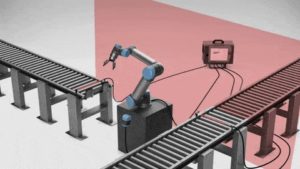
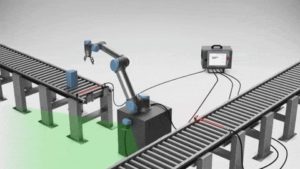
Safety planes in action12


Safety I/O: When this input safety function is triggered (via emergency buttons, sensors, etc.), a low signal is sent to the inputs and causes the safety system to transition to “reduced” mode.

Safety scanner13
Safety settings are effective in preventing many potential incidents. But what could happen if malicious actors targeted these measures in order to threaten human life?
Statement from the UR User Guide

Changing Safety Configurations Remotely

“The safety configuration settings shall only be changed in compliance with the risk assessment conducted by the integrator.14 If any safety parameter is changed the complete robot system shall be considered new, meaning that the overall safety approval process, including risk assessment, shall be updated accordingly.”
 

The exploitation process to remotely change the safety configuration is as follows:

Step 1.    Confirm the remote version by exploiting an authentication issue on the UR Dashboard Server.
Step 2.    Exploit a stack-based buffer overflow in UR Modbus TCP service, and execute commands as root.
Step 3.    Modify the safety.conf file. This file overrides all safety general limits, joints limits, boundaries, and safety I/O values.
Step 4.    Force a collision in the checksum calculation, and upload the new file. We need to fake this number since integrators are likely to write a note with the current checksum value on the hardware, as this is a common best practice.
Step 5.    Restart the robot so the safety configurations are updated by the new file. This should be done silently.
Step 6.    Move the robot in an arbitrary, dangerous manner by exploiting an authentication issue on the UR control service.

By analyzing and reverse engineering the firmware image ursys-CB3.1-3.3.4-310.img, I was able to understand the robot’s entry points and the services that allow other machines on the network to interact with the operating system. For this demo I used the URSim simulator provided by the vendor with the real core binary from the robot image. I was able to create modified versions of this binary to run partially on a standard Linux machine, even though it was clearer to use the simulator for this example exploit.

Different network services are exposed in the URControl core binary, and most of the proprietary protocols do not implement strong authentication mechanisms. For example, any user on the network can issue a command to one of these services and obtain the remote version of the running process (Step 1):


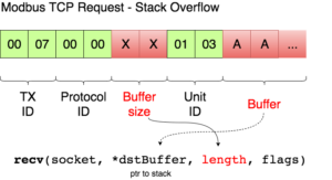
Now that I have verified the remote target is running a vulnerable image, ursys-CB3.1-3.3.4-310 (UR3, UR5 or UR10), I exploit a network service to compromise the robot (Step 2).The UR Modbus TCP service (port 502) does not provide authentication of the source of a command; therefore, an adversary could corrupt the robot in a state that negatively affects the process being controlled. An attacker with IP connectivity to the robot can issue Modbus read/write requests and partially change the state of the robot or send requests to actuators to change the state of the joints being controlled.It was not possible to change any safety settings by sending Modbus write requests; however, a stack-based buffer overflow was found in the UR Modbus TCP receiver (inside the URControl core binary).A stack buffer overflows with the recv function, because it uses a user-controlled buffer size to determine how many bytes from the socket will be copied there. This is a very common issue.

Before proceeding with the exploit, let’s review the exploit mitigations in place. The robot’s Linux kernel is configured to randomize (randomize_va_space=1 => ASLR) the positions of the stack, virtual dynamic shared object page, and shared memory regions. Moreover, this core binary does not allow any of its segments to be both writable and executable due to the “No eXecute” (NX) bit.

While overflowing the destination buffer, we also overflow pointers to the function’s arguments. Before the function returns, these arguments are used in other function calls, so we have to provide these calls with a valid value/structure. Otherwise, we will never reach the end of the function and be able to control the execution flow.
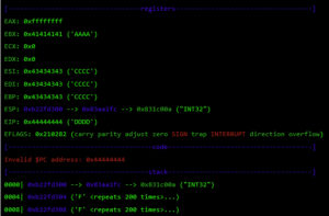
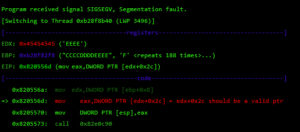
edx+0x2c is dereferenced and used as an argument for the call to 0x82e0c90. The problem appears afterwards when EBX (which is calculated from our previous controlled pointer on EDX) needs to also point to a structure where a file descriptor is obtained and is closed with “close” afterwards.

To choose a static address that might comply with these two requirements, I used the following static region, since all others change due to ASLR.

I wrote some scripts to find a suitable memory address and found 0x83aa1fc to be perfect since it suits both conditions:
      0x83aa1fc+0x2c points to valid memory -> 0x831c00a (“INT32”)
      0x83aa1fc+0x1014 contains 0 (nearly all this region is zeroed)
Now that I have met both conditions, execution can continue to the end of this function, and I get EIP control because the saved register on the stack was overflowed:


At this point, I control most of the registers, so I need to place my shellcode somewhere and redirect the execution flow there. For this, I used returned-oriented programming (ROP), the challenge will be to find enough gadgets to set everything I need for clean and reliable exploitation. Automatic ROP-chain tools did not work well for this binary, so I did it manually.First, I focus on my ultimate goal: to execute a reverse shell that connects to my machine. One key point when building a remote ROP-based exploit in Linux are system calls.Depending on the quality of gadgets that useint instructions I find, I will be able to use primitives such as write or dup2 to reuse the socket that was already created to return a shell or other post-exploitation strategies.In this binary, I only found one int 0x80 instruction. This is used to invoke system calls in Linux on x86. Because this is a one-shot gadget, I can only perform a single system call: I will use the execve system call to execute a program. This int 0x80 instruction requires setting up a register with the system call number (EAX in this case 0xb) and then set a register (EBX) that points to a special structure.This structure contains an array of pointers, each of which points to the arguments of the command to be executed.Because of how this vulnerability is triggered, I cannot use null bytes (0x00) on the request buffer. This is a problem because we need to send commands and arguments and also create an array of pointers that end with a null byte. To overcome this, I send a placeholder, like chunks of 0xFF bytes, and later on I replace them with 0x00 at runtime with ROP.In pseudocode this call would be (calls a TCP Reverse Shell):
 
 
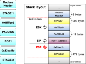
All the controlled data is in the stack, so first I will try to align the stack pointer (ESP) to my largest controlled section (STAGE 1). I divided the largest controlled sections into two stages, since they both can potentially contain many ROP gadgets. 

As seen before, at this point I control EBX and EIP. Next, I have to align ESP to any of the controlled segments so I can start doing ROP.

The following gadget (ROP1 0x8220efa) is used to adjust ESP:


This way ESP = ESP + EBX – 1 (STAGE 1 address in the stack). This aligns ESP to my STAGE 1 section. EBX should decrease ESP by 0x137 bytes, so I use the number 0xfffffec9 (4294966985) because when adding it to ESP, it wraps around to the desired value.
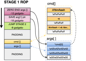
When the retn instruction of the gadget is executed, ROP gadgets at STAGE 1 start doing their magic. STAGE 1 of the exploit does the following:
  1. Zero out the at the end of the arguments structure. This way the processor will know that EXECVE arguments are only those three pointers.
  2. Save a pointer to our first command of cmd[] in our arguments structure.
  3. Jump to STAGE 2, because I don’t have much space here.
 

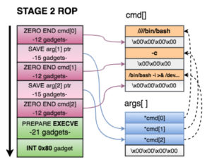
STAGE 2 of the exploit does the following:

  1. Zero out the xffxffxffxff at the end of each argument in cmd[].
  2. Save a pointer to the 2nd and 3rd argument of cmd[] in on our arguments structure.
  3. Prepare registers for EXECVE. As seen before, we needed
    1. EBX=*args[]
    2. EDX = 0
    3. EAX=0xb
  4. Call the int 0x80 gadget and execute the reverse shell.
Once the TCP reverse shell payload is executed, a connection is made back to my computer. Now I can execute commands and use sudo to execute commands as root in the robot controller.
 
Safety settings are saved in the safety.conf file (Step 3). Universal Robots implemented a CRC (STM-32) algorithm to provide integrity to this file and save the calculated checksum on disk. This algorithm does not provide any real integrity to the settings, as it is possible to generate collisions or calculate new checksum values for new settings overriding special files on the filesystem. I reversed how this calculation is being made for each safety setting and created an algorithm that replicates it. On the video demo, I did not fake the new CRC value to remain the same (located on top-right of the screen), even though this is possible and easy (Step 4).
 
Before modifying any safety setting on the robot, I setup a process that automatically starts a new instance of the robot controller after 25 seconds with the new settings. This will give me enough time to download, modify, and upload a new safety setting file. The following command sets up a new URControl process. I used Python since it allows me to close all current file descriptors of the running process when forking. Remember that I am forking from the reverse shell object, so I need to create a new process that does not inherit any of the file descriptors so they are closed when the parent URControl process dies (in order to restart and apply new safety settings).
 
 
Now I have 25 seconds to download the current file, modify it, calculate new CRC, reupload it, and kill the running URControl process (which has an older safety settings config). I can programmatically use the kill command to target the current URControl instance (Step 5).
 

Finally, I send this command to the URControl service in order to load the new installation we uploaded. I also close any popup that might appear on the UI.

 
Finally, an attacker can simply call the movej function in the URControl service to move joints remotely, with a custom speed and acceleration (Step 6). This is shown at the end of the video.

Once again, I see novel and expensive technology which is vulnerable and exploitable. A very technical bug, like a buffer overflow in one of the protocols, exposed the integrity of the entire robot system to remote attacks. We reported the complete flow of vulnerabilities to the vendors back in January, and they have yet to be patched.
What are we waiting for?
 
1 https://www.robots.com/faq/show/what-is-an-industrial-robot
2 https://www.roboticsbusinessreview.com/manufacturing/cobot-market-boom-lifts-universal-robots-fortunes-2016/
3 http://www.rethinkrobotics.com/blog/humans-and-collaborative-robots-working-together-in-grand-rapids-mi/ 
https://www.youtube.com/watch?v=G6_LCwu7dOg
4https://www.wired.com/2016/11/darpa-alias-autonomous-aircraft-aurora-sikorsky/
5 https://www.universal-robots.com/how-tos-and-faqs/faq/ur-faq/release-note-software-version-34xx/
6https://www.youtube.com/watch?v=PtncirKiBXQ&t=1s
7http://coro.etsmtl.ca/blog/?p=299
8 http://www.forensicmed.co.uk/pathology/head-injury/skull-fracture/
9https://www.universal-robots.com/case-stories/
11 https://academy.universal-robots.com
12https://academy.universal-robots.com
13Software_Manual_en_US.pdf – Universal Robots

Safety planes in action12


Safety I/O: When this input safety function is triggered (via emergency buttons, sensors, etc.), a low signal is sent to the inputs and causes the safety system to transition to “reduced” mode.

Safety Scanner 13

Safety settings are effective in preventing many potential incidents. But what could happen if malicious actors targeted these measures in order to threaten human life?

Statement from the UR User Guide

Changing Safety Configurations Remotely

“The safety configuration settings shall only be changed in compliance with the risk assessment conducted by the integrator.14 If any safety parameter is changed the complete robot system shall be considered new, meaning that the overall safety approval process, including risk assessment, shall be updated accordingly.”
 

The exploitation process to remotely change the safety configuration is as follows:

Step 1.    Confirm the remote version by exploiting an authentication issue on the UR Dashboard Server.
Step 2.    Exploit a stack-based buffer overflow in UR Modbus TCP service, and execute commands as root.
Step 3.    Modify the safety.conf file. This file overrides all safety general limits, joints limits, boundaries, and safety I/O values.
Step 4.    Force a collision in the checksum calculation, and upload the new file. We need to fake this number since integrators are likely to write a note with the current checksum value on the hardware, as this is a common best practice.
Step 5.    Restart the robot so the safety configurations are updated by the new file. This should be done silently.
Step 6.    Move the robot in an arbitrary, dangerous manner by exploiting an authentication issue on the UR control service.

By analyzing and reverse engineering the firmware image ursys-CB3.1-3.3.4-310.img, I was able to understand the robot’s entry points and the services that allow other machines on the network to interact with the operating system. For this demo I used the URSim simulator provided by the vendor with the real core binary from the robot image. I was able to create modified versions of this binary to run partially on a standard Linux machine, even though it was clearer to use the simulator for this example exploit.

Different network services are exposed in the URControl core binary, and most of the proprietary protocols do not implement strong authentication mechanisms. For example, any user on the network can issue a command to one of these services and obtain the remote version of the running process (Step 1):


Now that I have verified the remote target is running a vulnerable image, ursys-CB3.1-3.3.4-310 (UR3, UR5 or UR10), I exploit a network service to compromise the robot (Step 2).The UR Modbus TCP service (port 502) does not provide authentication of the source of a command; therefore, an adversary could corrupt the robot in a state that negatively affects the process being controlled. An attacker with IP connectivity to the robot can issue Modbus read/write requests and partially change the state of the robot or send requests to actuators to change the state of the joints being controlled.It was not possible to change any safety settings by sending Modbus write requests; however, a stack-based buffer overflow was found in the UR Modbus TCP receiver (inside the URControl core binary).A stack buffer overflows with the recv function, because it uses a user-controlled buffer size to determine how many bytes from the socket will be copied there. This is a very common issue.

Before proceeding with the exploit, let’s review the exploit mitigations in place. The robot’s Linux kernel is configured to randomize (randomize_va_space=1 => ASLR) the positions of the stack, virtual dynamic shared object page, and shared memory regions. Moreover, this core binary does not allow any of its segments to be both writable and executable due to the “No eXecute” (NX) bit.

While overflowing the destination buffer, we also overflow pointers to the function’s arguments. Before the function returns, these arguments are used in other function calls, so we have to provide these calls with a valid value/structure. Otherwise, we will never reach the end of the function and be able to control the execution flow.

edx+0x2c is dereferenced and used as an argument for the call to 0x82e0c90. The problem appears afterwards when EBX (which is calculated from our previous controlled pointer on EDX) needs to also point to a structure where a file descriptor is obtained and is closed with “close” afterwards.

To choose a static address that might comply with these two requirements, I used the following static region, since all others change due to ASLR.

I wrote some scripts to find a suitable memory address and found 0x83aa1fc to be perfect since it suits both conditions:
      0x83aa1fc+0x2c points to valid memory -> 0x831c00a (“INT32”)
      0x83aa1fc+0x1014 contains 0 (nearly all this region is zeroed)
Now that I have met both conditions, execution can continue to the end of this function, and I get EIP control because the saved register on the stack was overflowed:

At this point, I control most of the registers, so I need to place my shellcode somewhere and redirect the execution flow there. For this, I used returned-oriented programming (ROP), the challenge will be to find enough gadgets to set everything I need for clean and reliable exploitation. Automatic ROP-chain tools did not work well for this binary, so I did it manually.
 
First, I focus on my ultimate goal: to execute a reverse shell that connects to my machine. One key point when building a remote ROP-based exploit in Linux are system calls. Depending on the quality of gadgets that use int instructions I find, I will be able to use primitives such as write or dup2 to reuse the socket that was already created to return a shell or other post-exploitation strategies.

In this binary, I only found one int 0x80 instruction. This is used to invoke system calls in Linux on x86. Because this is a one-shot gadget, I can only perform a single system call: I will use the execve system call to execute a program. This int 0x80 instruction requires setting up a register with the system call number (EAX in this case 0xb) and then set a register (EBX) that points to a special structure. This structure contains an array of pointers, each of which points to the arguments of the command to be executed.
 
Because of how this vulnerability is triggered, I cannot use null bytes (0x00) on the request buffer. This is a problem because we need to send commands and arguments and also create an array of pointers that end with a null byte. To overcome this, I send a placeholder, like chunks of 0xFF bytes, and later on I replace them with 0x00 at runtime with ROP.
 
In pseudocode this call would be (calls a TCP Reverse Shell):
 
 
All the controlled data is in the stack, so first I will try to align the stack pointer (ESP) to my largest controlled section (STAGE 1). I divided the largest controlled sections into two stages, since they both can potentially contain many ROP gadgets. 

As seen before, at this point I control EBX and EIP. Next, I have to align ESP to any of the controlled segments so I can start doing ROP.
The following gadget (ROP1 0x8220efa) is used to adjust ESP:
 
 
This way ESP = ESP + EBX – 1 (STAGE 1 address in the stack). This aligns ESP to my STAGE 1 section. EBX should decrease ESP by 0x137 bytes, so I use the number 0xfffffec9 (4294966985) because when adding it to ESP, it wraps around to the desired value.
When the retn instruction of the gadget is executed, ROP gadgets at STAGE 1 start doing their magic. STAGE 1 of the exploit does the following:
  1. Zero out the at the end of the arguments structure. This way the processor will know that EXECVE arguments are only those three pointers.
  2. Save a pointer to our first command of cmd[] in our arguments structure.
  3. Jump to STAGE 2, because I don’t have much space here.
 

STAGE 2 of the exploit does the following:

  1. Zero out the xffxffxffxff at the end of each argument in cmd[].
  2. Save a pointer to the 2nd and 3rd argument of cmd[] in on our arguments structure.
  3. Prepare registers for EXECVE. As seen before, we needed
    1. EBX=*args[]
    2. EDX = 0
    3. EAX=0xb
  4. Call the int 0x80 gadget and execute the reverse shell.
Once the TCP reverse shell payload is executed, a connection is made back to my computer. Now I can execute commands and use sudo to execute commands as root in the robot controller.
 
Safety settings are saved in the safety.conf file (Step 3). Universal Robots implemented a CRC (STM-32) algorithm to provide integrity to this file and save the calculated checksum on disk. This algorithm does not provide any real integrity to the settings, as it is possible to generate collisions or calculate new checksum values for new settings overriding special files on the filesystem. I reversed how this calculation is being made for each safety setting and created an algorithm that replicates it. On the video demo, I did not fake the new CRC value to remain the same (located on top-right of the screen), even though this is possible and easy (Step 4).
 
Before modifying any safety setting on the robot, I setup a process that automatically starts a new instance of the robot controller after 25 seconds with the new settings. This will give me enough time to download, modify, and upload a new safety setting file. The following command sets up a new URControl process. I used Python since it allows me to close all current file descriptors of the running process when forking. Remember that I am forking from the reverse shell object, so I need to create a new process that does not inherit any of the file descriptors so they are closed when the parent URControl process dies (in order to restart and apply new safety settings).
 
 
Now I have 25 seconds to download the current file, modify it, calculate new CRC, reupload it, and kill the running URControl process (which has an older safety settings config). I can programmatically use the kill command to target the current URControl instance (Step 5).
 

Finally, I send this command to the URControl service in order to load the new installation we uploaded. I also close any popup that might appear on the UI.


Finally, an attacker can simply call the movej function in the URControl service to move joints remotely, with a custom speed and acceleration (Step 6). This is shown at the end of the video.

Once again, I see novel and expensive technology which is vulnerable and exploitable. A very technical bug, like a buffer overflow in one of the protocols, exposed the integrity of the entire robot system to remote attacks. We reported the complete flow of vulnerabilities to the vendors back in January, and they have yet to be patched.

What are we waiting for?

 
1 https://www.robots.com/faq/show/what-is-an-industrial-robot
2 https://www.roboticsbusinessreview.com/manufacturing/cobot-market-boom-lifts-universal-robots-fortunes-2016/
3 http://www.rethinkrobotics.com/blog/humans-and-collaborative-robots-working-together-in-grand-rapids-mi/ 
https://www.youtube.com/watch?v=G6_LCwu7dOg
4https://www.wired.com/2016/11/darpa-alias-autonomous-aircraft-aurora-sikorsky/
5 https://www.universal-robots.com/how-tos-and-faqs/faq/ur-faq/release-note-software-version-34xx/
6https://www.youtube.com/watch?v=PtncirKiBXQ&t=1s
7http://coro.etsmtl.ca/blog/?p=299
8 http://www.forensicmed.co.uk/pathology/head-injury/skull-fracture/
9https://www.universal-robots.com/case-stories/
11 https://academy.universal-robots.com
12https://academy.universal-robots.com
13Software_Manual_en_US.pdf – Universal Robots
RESEARCH | March 1, 2017

Hacking Robots Before Skynet

Robots are going mainstream in both private and public sectors – on military missions, performing surgery, building skyscrapers, assisting customers at stores, as healthcare attendants, as business assistants, and interacting closely with our families in a myriad of ways. Robots are already showing up in many of these roles today, and in the coming years they will become an ever more prominent part of our home and business lives. But similar to other new technologies, recent IOActive research has found robotic technologies to be highly insecure in a variety of ways that could pose serious threats to the people and organizations they operate in and around.
 
This blog post is intended to provide a brief overview of the full paper we’ve published based on this research, in which we discovered critical cybersecurity issues in several robots from multiple vendors. The goal is to make robots more secure and prevent vulnerabilities from being used maliciously by attackers to cause serious harm to businesses, consumers, and their surroundings. The paper contains more information about the research, findings, and cites many sources used in compiling the information presented in the paper and this post.
 
Robot Adoption and Cybersecurity
Robots are already showing up in thousands of homes and businesses. As many of these “smart” machines are self-propelled, it is important that they’re secure, well protected, and not easy to hack. If not, instead of helpful resources they could quickly become dangerous tools capable of wreaking havoc and causing substantive harm to their surroundings and the humans they’re designed to serve.
 
We’re already experiencing some of the consequences of substantial cybersecurity problems with Internet of Things (IoT) devices that are impacting the Internet, companies and commerce, and individual consumers alike. Cybersecurity problems in robots could have a much greater impact. When you think of robots as computers with arms, legs, or wheels, they become kinetic IoT devices that, if hacked, can pose new serious threats we have never encountered before.
 
With this in mind, we decided to attempt to hack some of the more popular home, business, and industrial robots currently available on the market. Our goal was to assess the cybersecurity of current robots and determine potential consequences of possible cyberattacks. Our results show how insecure and susceptible current robot technology is to cyberattacks, confirming our initial suspicions.
 
Cybersecurity Problems in Today’s Robots
We used our expertise in hacking computers and embedded devices to build a foundation of practical cyberattacks against robot ecosystems. A robot ecosystem is usually composed of the physical robot, an operating system, firmware, software, mobile/remote control applications, vendor Internet services, cloud services, networks, etc. The full ecosystem presents a huge attack surface with numerous options for cyberattacks.
 
We applied risk assessment and threat modeling tools to robot ecosystems to support our research efforts, allowing us to prioritize the critical and high cybersecurity risks for the robots we tested. We focused on assessing the most accessible components of robot ecosystems, such as mobile applications, operating systems, firmware images, and software. Although we didn’t have all the physical robots, it didn’t impact our research results. We had access to the core components, which provide most of the functionality for the robots; we could say these components “bring them to life.”
 
Our research covered home, business, and industrial robots, as well as the control software used by several other robots. The specific robot vendors evaluated in the research are identified in the published research paper.
 
We found nearly 50 cybersecurity vulnerabilities in the robot ecosystem components, many of which were common problems. While this may seem like a substantial number, it’s important to note that our testing was not even a deep, extensive security audit, as that would have taken a much larger investment of time and resources. The goal for this work was to gain a high level sense of how insecure today’s robots are, which we accomplished. We will continue researching this space and go deeper in future projects.
 
An explanation of each main cybersecurity issue discovered is available in the published research paper, but the following is a high-level (non-technical) list of what we found:
·         Insecure Communications
·         Authentication Issues
·         Missing Authorization
·         Weak Cryptography
·         Privacy Issues
·         Weak Default Configuration
·         Vulnerable Open Source Robot Frameworks and Libraries
 
We observed a broad problem in the robotics community: researchers and enthusiasts use the same – or very similar – tools, software, and design practices worldwide. For example, it is common for robots born as research projects to become commercial products with no additional cybersecurity protections; the security posture of the final product remains the same as the research or prototype robot. This practice results in poor cybersecurity defenses, since research and prototype robots are often designed and built with few or no protections. This lack of cybersecurity in commercial robots was clearly evident in our research.
 
Cyberattacks on Robots

Our research uncovered both critical- and high-risk cybersecurity problems in many robot features. Some of them could be directly abused, and others introduced severe threats. Examples of some of the common robot features identified in the research as possible attack threats are as follows:

  • Microphones and Cameras
  • External Services Interaction
  • Remote Control Applications
  • Modular Extensibility
  • Network Advertisement
  • Connection Ports
A full list with descriptions for each is available in the published paper.
 
New technologies are typically prone to security problems, as vendors prioritize time-to-market over security testing. We have seen vendors struggling with a growing number of cybersecurity issues in multiple industries where products are growing more connected, including notably IoT and automotive in recent years. This is usually the result of not considering cybersecurity at the beginning of the product lifecycle; fixing vulnerabilities becomes more complex and expensive after a product is released.
 
The full paper provides an overview of the many implications of insecure robots as they become more prominent in home, business, industry, healthcare, and other applications. We’ve also included many recommendations in the paper for ways to design and build robotic technology more securely based on our findings.
 
Click here for more information on the research and to view the full paper for additional details and descriptions.   
INSIGHTS | September 1, 2016

Five Attributes of an Effective Corporate Red Team

After talking recently with colleagues at IOActive as well as some heads of industry-leading red teams, we wanted to share a list of attributes that we believe are key to any effective Red Team.

[ NOTE: For debate about the relevant terminology, we suggest Daniel’s post titled The Difference Between Red, Blue, and Purple Teams. ]

To be clear, we think there can be significant variance in how Red Teams are built and managed, and we believe there are likely multiple routes to success. But we believe there are a few key attributes that all (or at least most) corporate Red Teams should have as part of their program. These are:

  1. Organizational Independence
  2. Defensive Coordination
  3. Continuous Operation
  4. Adversary Emulation
  5. Efficacy Measurement

Let’s look at each of these.

Organizational Independence is the requirement that the Red Team be able to effectively act as a real-world attacker in terms of scope, tools, and techniques employed. Many organizations restrict their Red Teams to such a degree that they’re basically impotent, which in turn lulls the company into a false sense of security.

Defensive Coordination is the requirement that Red Teams regularly interact with their counterparts on the defensive side to ensure the organization is learning from their activities. If a Red Team is effective on its own, but doesn’t share its knowledge and successes with the defense in order make it stronger, then the Red Team has lost sight of its purpose.

Continuous Operation is the requirement that the organization remain under constant, rolling attack by the Red Team, which is the polar opposite of short, penetration-test style engagements. Red Teams should operate through campaigns that span weeks or months in duration, and both the defensive teams and the general user population should know that at any moment, of any day, they could be targeted by both a Red Team campaign of some sort, or by a real attacker.

Adversary Emulation is the requirement that Red Team campaigns should be regularly updated based on the actual tools, techniques, and processes employed by real-world attackers. If cyber-criminals are doing X this quarter, let’s emulate that. If we’re seeing some state actors doing Y this year, let’s emulate that. If you’re not simulating—to some significant degree—the techniques being used by actual attackers, the Red Team is providing questionable value.

Efficacy Measurement is the requirement that Red Teams know how effective they are at improving the security posture of the organization. If we can’t tell a clear story around how our defenses are improving, i.e., that it’s getting increasingly more difficult to compromise, move laterally, and achieve attacker goals, then you’re getting limited value from any work that’s being done.

Summary

Here’s a pointed capture of those points:

  • If your group is significantly restricted in its scope and capabilities by the organization, you probably don’t have an effective Red Team
  • If your group doesn’t regularly work hand-in-hand with the defensive side of the organization in order to improve the organization’s security posture, you probably don’t have an effective Red Team
  • If your internal or external service operates based on projects that happen once in a while rather than being staggered and continuous, you probably don’t have an effective Red Team
  • If you aren’t constantly updating your attack campaigns based on new intelligence on actual threat actors, you probably don’t have an effective Red Team
  • If you aren’t closely monitoring the effectiveness of the attack campaigns (and the responses to them by the defense) over time, you probably don’t have an effective Red Team

There are many other components of a solid Red Team that were not mentioned—top-end malware kits, elite security talent, deep understanding of the attacker mindset, etc.—but we think these five components are both most fundamental and most lacking.

As always, we would love to hear from other security types who might have a differing opinion. All of our positions are subject to change through exposure to compelling arguments and/or data.
INSIGHTS | March 22, 2016

Inside the IOActive Silicon Lab: Interpreting Images

In the post “Reading CMOS layout,” we discussed understanding CMOS layout in order to reverse-engineer photographs of a circuit to a transistor-level schematic. This was all well and good, but I glossed over an important (and often overlooked) part of the process: using the photos to observe and understand the circuit’s actual geometry.


Optical Microscopy

Let’s start with brightfield optical microscope imagery. (Darkfield microscopy is rarely used for semiconductor work.) Although reading lower metal layers on modern deep-submicron processes does usually require electron microscopy, optical microscopes still have their place in the reverse engineer’s toolbox. They are much easier to set up and run quickly, have a wider field of view at low magnifications, need less sophisticated sample preparation, and provide real-time full-color imagery. An optical microscope can also see through glass insulators, allowing inspection of some underlying structures without needing to deprocess the device.
 
This can be both a blessing and a curse. If you can see underlying structures in upper-layer images, it can be much easier to align views of different layers. But it can also be much harder to tell what you’re actually looking at! Luckily, another effect comes to the rescue – depth of field.


Depth of field

When using an objective with 40x power or higher, a typical optical microscope has a useful focal plane of less than 1 µm. This means that it is critical to keep the sample stage extremely flat – a slope of only 100 nm per mm (0.005 degrees) can result in one side of a 10x10mm die being in razor-sharp focus while the other side is blurred beyond recognition.
 
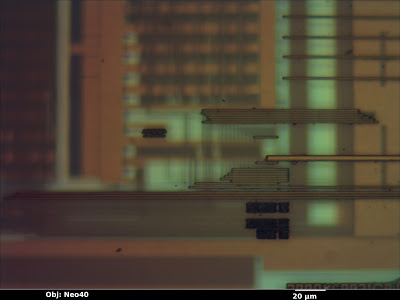
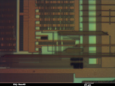
In the image below (from a Micrel KSZ9021RN gigabit Ethernet PHY) the top layer is in sharp focus but all of the features below are blurred—the deeper the layer, the less easy it is to see.
We as reverse engineers can use this to our advantage. By sweeping the focus up or down, we can get a qualitative feel for which wires are above, below, or on the same layer as other wires. Although it can be useful in still photos, the effect is most intuitively understood when looking through the eyepiece and adjusting the focus knob by hand. Compare the previous image to this one, with the focal plane shifted to one of the lower metal layers.
I also find that it’s sometimes beneficial to image a multi-layer IC using a higher magnification than strictly necessary, in order to deliberately limit the depth of field and blur out other wiring layers. This can provide a cleaner, more easily understood image, even if the additional resolution isn’t necessary.


Color

Another important piece of information the optical microscope provides is color.  The color of a feature under an optical microscope is typically dependent on three factors:
  •       Material color
  •        Orientation of the surface relative to incident light
  •        Thickness of the glass/transparent material over it

 
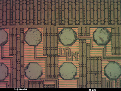
Material color is the easiest to understand. A flat, smooth surface of a substance with nothing on top will have the same color as the bulk material. The octagonal bond pads in the image below (a Xilinx XC3S50A FPGA), for example, are made of bare aluminum and show up as a smooth silvery color, just as one would expect. Unfortunately, most materials used in integrated circuits are either silvery (silicon, polysilicon, aluminum, tungsten) or clear (silicon dioxide or nitride). Copper is the lone exception.
 
Orientation is another factor to consider. If a feature is tilted relative to the incident light, it will be less brightly lit. The dark squares in the image below are vias in the upper metal layer which go down to the next layer; the “sag” in the top layer is not filled in this process so the resulting slopes show up as darker. This makes topography visible on an otherwise featureless surface.
The third property affecting observed color of a feature is the glass thickness above it. When light hits a reflective surface under a transparent, reflective surface, some of the beam bounces off the lower surface and some bounces off the top of the glass. The two beams interfere with each other, producing constructive and destructive interference at wavelengths equal to multiples of the glass thickness.
 
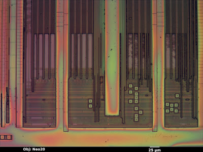
This is the same effect responsible for the colors seen in a film of oil floating on a puddle of water–the reflections from the oil’s surface and the oil-water interface interfere. Since the oil film is not exactly the same thickness across the entire puddle, the observed colors vary slightly. In the image above, the clear silicon nitride passivation is uniform in thickness, so the top layer wiring (aluminum, mostly for power distribution) shows up as a uniform tannish color. The next layer down has more glass over it and shows up as a slightly different pink color.
 
Compare that to the image below (an Altera EPM3064A CPLD). The thickness of the top passivation layer varies significantly across the die surface, resulting in rainbow-colored fringes.
 

Electron Microscopy

The scanning electron microscope is the preferred tool for imaging finer pitch features (below about 250 nm). Due to the smaller wavelength of electron beams as compared to visible light, this tool can obtain significantly higher resolutions.
 
The basic operating principle of a SEM is similar to an old-fashioned CRT display: electromagnets move a beam of electrons in a vacuum chamber in a raster-scan pattern over the sample. At each pixel, the beam interacts with the sample, producing several forms of radiation that the microscope can detect and use for imaging.
 
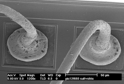
Electron microscopy in general has an extremely high depth of field, making it very useful for imaging 3D structures. The image below (copper bond wires on a Microchip PIC12F683) has about the same field of view as the optical images from the beginning of this article, but even from a tilted perspective the entire loop of wire is in sharp focus.


Secondary Electron Images

The most common general-purpose image detector for the SEM is the secondary electron detector. When a high-energy electron from the scanning beam grazes an atom in the sample, it sometimes dislodges an electron from the outer shell. Secondary electrons have very low energy, and will slow to a stop after traveling a fairly short distance. As a result, only those generated very near the surface of the sample will escape and be detected.
 
This makes secondary electron images very sensitive to topography. Outside edges, tilted surfaces, and small point features (dust and particulates) show up brighter than a flat surface because a high percentage of the secondary electrons are generated near exposed surfaces of the specimen. Inward-facing edges show up dimmer than a flat surface because a high percentage of the secondary electrons are absorbed in the material.
 
The general appearance of a secondary electron image is similar to a surface lit up with a floodlight. The eye position is that of the objective lens, and the “light source” appears to come from the position of the secondary electron detector.
 
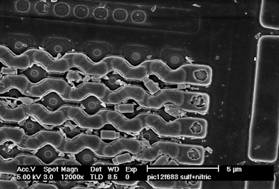
In the image below (the polysilicon layer of a Microchip PIC12F683 before cleaning), the polysilicon word lines running horizontally across the memory array have bright edges, which shows that they are raised above the background. The diamond-shaped source/drain areas have dark “shadowed” edges, showing that they are lower than their surroundings (and thus many of the secondary electrons are being absorbed). The dust particles and loose tungsten via plugs scattered around the image show up very brightly because they have so much exposed surface area.
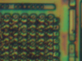
Compare the above SEM view to the optical image of the same area below. Note that the SEM image has much higher resolution, but the optical image reveals (through color changes) thickness variations in the glass layer that are not obvious in the SEM. This can be very helpful when trying to gauge progress or uniformity of an etch/polish operation.
In addition to the primary contrast mechanism discussed above, the efficiency of secondary electron emission is weakly dependent on the elemental composition of the material being observed. For example, at 20 kV the number of secondary electrons produced for a given beam current is about four times higher for tungsten than for silicon (see this paper). While this may lead to some visible contrast in a secondary electron image, if elemental information is desired, it would be preferable to use a less topography-sensitive imaging mode.
 

Backscattered Electron Images

Secondary electron imaging does not work well on flat specimens, such as a die that has been polished to remove upper metal layers or a cross section. Although it’s often possible to etch such a sample to produce topography for imaging in secondary electron mode, it’s usually easier to image the flat sample using backscatter mode.
 
When a high-energy beam electron directly impacts the nucleus of an atom in the sample, it will bounce back at high speed in the approximate direction it came from. The probability of such a “backscatter” event happening depends on the atomic number Z of the material being imaged. Since backscatters are very energetic, the surrounding material does not easily absorb them. As a result, the appearance of the resulting image is not significantly influenced by topography and contrast is primarily dependent on material (Z-contrast).
 
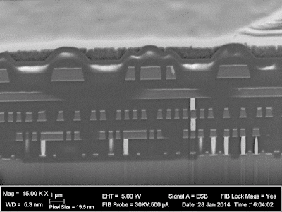
In the image below (cross section of a Xilinx XC2C32A CPLD), the silicon substrate (bottom, Z=14) shows up as a medium gray. The silicon dioxide insulator between the wires is darker due to the lower average atomic number (Z=8 for oxygen). The aluminum wires (Z=13) are about the same color as the silicon, but the titanium barrier layer (Z=22) above and below is significantly brighter. The tungsten vias (Z=74) are extremely bright white. Looking at the bottom right where the via plugs touch the silicon, a thin layer of cobalt (Z=27) silicide is visible.

Depending on the device you are analyzing, any or all of these three imaging techniques may be useful. Knowledge of the pros and cons of these techniques and the ability to interpret their results are key skills for the semiconductor reverse engineer.
INSIGHTS | February 14, 2010

Infineon / ST Mesh Comparison

Given all the recent exposure from our Infineon research, we have had numerous requests regarding the ST mesh architecture and how Infineon’s design compares to the ST implementation.

Both devices are a 4 metal ~140 nanometer process.  Rather than have us tell you who we think is stronger (it’s pretty obvious), we’d like to see your comments on what you the readers think!

The Infineon mesh consists of 5 zones with 4 circuits per zone.  This means the surface of the die is being covered by 20 different electrical circuits.

The ST mesh consists of a single wire routed zig-zag across the die.  It usually begins next to the VDD pad and ends at the opposite corner of the die.  The other wires are simply GND aka ground fingers.  On recent designs, we have caught ST using a few of the grounds to tie gates low (noise isolation of extra, unused logic we believe).

Zooming in at 15,000 magnification, the details of each mesh really begin to show.  Where at lower resolutions, the Infineon mesh looked dark and solid but as you can see, it is not.

In the Infineon scheme above, each colored wire is the same signal (4 of them per zone).  Each color will be randomly spaced per chip design and is connected at either the top or bottom of the die via Metal 3 inter-connects.

The ST simply has the single conductor labeled in red.  All green are the fingers of ground which can be usually cut away (removed) without penalty.  The latest ST K7xxx devices have a signal present that appears analog.  A closer look and a few minutes of testing proved it to simply need to be held high (logic ‘1’) at the sampling side of the line.  Interesting how ST tried to obscure the signal.

Infineon does not permanently penalize you if the mesh is not properly repaired and the device is powered up.

ST will permanently penalize you with a bulk-erase of the non-volatile memory (NVM) areas if the sense line (red) is ever a logic low (‘0’) with power applied (irrelevant of reset/clock condition).

You tell us your opinion what you think security wise.

INSIGHTS | February 13, 2008

Atmel CryptoMemory AT88SC153/1608 :: Security Alert

A “backdoor” has been discovered by Flylogic Engineering in the Atmel AT88SC153 and AT88SC1608 CryptoMemory.

Before we get into this more, we want to let you know immediately that this backdoor only involves the AT88SC153/1608 and no other CryptoMemory devices.

The backdoor involves restoring an EEPROM fuse with Ultra-Violet light (UV).  Once the fuse bit has been returned to a ‘1’, all memory contents is permitted to be read or written in the clear (unencrypted).

Normally in order to do so, you need to either authenticate to the device or use a read-once-given “secure code” as explained in the AT88SC153 datasheet and the AT88SC1608 datasheet.

For those of you who are unfamiliar Atmel’s CryptoMemory, they are serial non-volatile memory (EEPROM) that support a clear or secure channel of communications between a host (typically an MCU) and the memory.  What is unique about the CryptoMemory are their capabilities in establishing the secure channel (authenticating to the host, etc).

These device includes:

High-security Memory Including Anti-wiretapping

64-bit Authentication Protocol

Secure Checksum

Configurable Authentication Attempts Counter

These device includes:

  • Multiple Sets of Passwords
  • Specific Passwords for Read and Write
  • Password Attempts Counters
  • Selectable Access Rights by Zone
  • High-security Memory Including Anti-wiretapping
  • 64-bit Authentication Protocol
  • Secure Checksum
  • Configurable Authentication Attempts Counter

Section 5 of the datasheet labled, “Fuses” clearly states, “Once blown, these EEPROM fuses can not be reset.

This statement is absolutely false.  UV light will erase the fuses back to a ‘1’ state.  Care must be used to not expose the main memory to the UV or else it too will erase itself.

We are not going to explain the details of how to use the UV light to reset the fuse.  We have tried to contact Atmel but have not heard anything back from them.

Reading deeper into the datasheet under Table 5-1, Atmel writes, “When the fuses are all “1”s, read and write are allowed in the entire memory.

As strange as it reads, they really do mean even if you have setup security rules in the configuration memory, it doesn’t matter.  The fuses override everything and all memory areas are readable in the clear without the need for authentication or encrypted channel!  The attacker can even see what the “Secure Code” is (it is not given out in the public documentation, nor with samples).  Atmel was even kind enough to leave test pads everywhere so various levels of attackers can learn (entry to expert).

Our proof of concept was tested on samples we acquired through Atmel’s website.  Atmel offers samples to anyone however they do not give out the “Secure code” as mentioned above.
  • The secure code of the AT88SC153 samples was “$D_ $F_ $7_”.
  • The secure code of the AT88SC1608 was “$7_ $5_ $5_”.

We are not going to show you the low nibble of the 3 bytes to make sure we don’t give the code out to anyone.  This is enough proof to whoever else knows this code.  That person(s) can clearly see we know their transport code which appears to be common to all samples (e.g. All die on a wafer contain the same secure code until a customer orders parts at which time that customer receives their own secure code.).  A person reading this cannot guess the secure code in because there are 12 bits to exhaustively search out and you only have 8 tries ;).

Of all the other CryptoMemory products, only the AT88SC153/1608 has this backdoor.  We have successfully analyzed the entire CryptoMemory product line and can say that the backdoor doesn’t exist in any other CryptoMemory part.  None of the CryptoMemory parts are actually as “secure” as they make it seem.  The words, “Smoke n’ Mirrors” comes to mind (It is almost always like that).  In this particular category of CryptoMemory, there are two parts, the AT88SC153 and the larger AT88SC1608.

Thus the questions-
    • Why has Atmel only backdoored this part (NSA for you conspiracists)?
    • Who was the original intended customer supposed to be?
    • Was the original intention of these devices to be used in a product that used some kind of cryptography?

If the above was true, was this device originally intended to be a cryptographic key-vault?

All these questions come to mind because the backdoor makes it so easy to extract the contents of the device they want you to trust.  Some of you may be familiar with the GSM A5/1 algorithm having certain bits of the key set to a fixed value.

Judging by the wording of the documentation, Atmel gives the appearance that CryptoMemory are the perfect choice for holding your most valuable secrets.

Give us your thoughts…

INSIGHTS | January 24, 2008

ATMEGA88 Teardown

An 8k FLASH, 512 bytes EEPROM, 512 bytes SRAM CPU operating 1:1 with the external world unlike those Microchip PIC’s we love to write up about :).

It’s a 350 nanometer (nm), 3 metal layer device fabricated in a CMOS process.  It’s beautiful to say the least;  We’ve torn it down and thought we’d blog about it!

The process Atmel uses on their .35 micrometer (um) technology is awesome.

Using a little HydroFluoric Acid (HF) and we partially removed the top metal layer (M3).  Everything is now clearly visible for our analysis. After delaying earlier above, we can now recognize features that were otherwise hidden such as the Static RAM (SRAM) and the 32 working registers.

As we mentioned earlier, we used the word, “awesome” because check this out- It’s so beautifully layed out that we can etch off just enough of the top metal layer to leave it’s residue so it’s still visible depending on the focal point of the microscope!  This is very important.

We removed obscuring metal but can still see where it went (woot!).The two photos above contain two of the 30+ configuration fuses present however it makes a person wonder why did Atmel cover the floating gate of the upper fuse with a plate of metal (remember the microchip article with the plates over the floating gates?)

We highlighted a track per fuse in the above photos.  What do you think these red tracks might represent?

INSIGHTS | January 22, 2008

Security Mechanism of PIC16C558,620,621,622

Last month we talked about the structure of an AND-gate layed out in Silicon CMOS.  Now, we present to you how this AND gate has been used in Microchip PICs such as PIC16C558, PIC16C620, PIC16C621, PIC16C622, and a variety of others.

If you wish to determine if this article relates to a particular PIC you may be in possession of, you can take an windowed OTP part (/JW) and set the lock-bits.  If after 10 minutes in UV, it still says it’s locked, this article applies to your PIC.

IF THE PART REMAINS LOCKED, IT CANNOT BE UNLOCKED SO TEST AT YOUR OWN RISK.

The picture above is the die of the PIC16C558 magnified 100x.  The PIC16C620-622 look pretty much the same.  If there are letters after the final number, the die will be most likely, “shrunk” (e.g. PIC16C622 vs PIC16C622A).

Our area of concern is highlighted above along with a zoom of the area.

When magnified 500x, things become clear.  Notice the top metal (M2) is covering our DUAL 2-Input AND gate in the red box above.We previously showed you one half of the above area.  Now you can see that there is a pair of 2-input AND gates.  This was done to offer two security lock-bits for memory regions (read the datasheet on special features of the CPU).Stripping off that top metal (M2) now clearly shows us the bussing from two different areas to keep the part secure.  Microchip went the extra step of covering the floating gate of the main easilly discoverable fuses with metal to prevent UV from erasing a locked state.  The outputs of those two fuses also feed into logic on the left side of the picture to tell you that the part is locked during a device readback of the configuration fuses.

This type of fuse is protected by multiple set fuses of which only some are UV-erasable.

The AND gates are ensuring all fuses are erased to a ‘1’ to “unlock” the device.

What does this mean to an attacker?  It means, go after the inal AND gate if you want to forcefully unlock the CPU.  The outputs of the final AND gate stage run underneather VDD!! (The big mistake Microchip made).  Two shots witha laser-cutter and we can short the output stages “Y” from the AND-gate to a logic ‘1’ allowing readback of the memories (the part will still say it is locked).Stripping off the lower metal layer (M1) reveils the Poly-silicon layer.

What have we learned from all this?

    • A lot of time and effort went into the design of this series of security mechanisms.
    • These are the most secure Microchip PICs of ALL currently available.  The latest ~350-400nm 3-4 metal layer PICs are less secure than the
    • Anything made by human can be torn down by human!

:->

INSIGHTS | December 29, 2007

AND Gates in logic

As we prepare for the New Year, we wanted to leave you with a piece of logic taken out of an older PIC16C series microcontroller. We want you to guess which micro(s) this gate (well the pair of them) would be found in. After the New Year, we’ll right up on the actual micro(s) and give the answer :).

An AND gate in logic is basically a high (logic ‘1’) on all inputs to the gate. For our example, we’re discussing the 2 input AND. It should be noted that this is being built from a NAND and that a NAND would require 2 less gates than an AND.

The truth table is all inputs must be a ‘1’ to get a ‘1’ on the output (Y). If any input is a ‘0’, Y = ‘0’.

There are 2 signals we labeled ‘A’ and ‘B’ routed in the Poly layer of the substrate (under all the metal). This particular circuit is not on the top of the device and had another metal layer above it (Metal 2 or M2). So technically, you are seeing Metal 1 (M1) and lower (Poly, Diffusion).

It’s quickly obvious that this is an AND gate but it could also be a NAND by removing the INVERTER and taking the ‘!Y’ signal instead of ‘Y’.

The red box to the left is the NAND leaving the red box to the right being the inverter creating our AND gate.

The upper green area are PFET’s with the lower green area being NFET’s.

After stripping off M1, we now can clearly see the Poly layer and begin to recognize the circuit.

This is a short article and we will follow up after the New Year begins. This is a single AND gate but was part of a pair. From the pair, this was the right side. We call them a pair because they work together to provide the security feature on some of the PIC16C’s we’re asking you to guess which ones 🙂

Happy Holidays and Happy Guessing!

INSIGHTS | December 17, 2007

ST201: ST16601 Smartcard Teardown

ST SmartCards 201 – Introduction to the ST16601 Secure MCU

This piece is going to be split into two articles-

    • The first being this article is actually a primer on all of the ST16XYZ series smartcards using this type of Mesh technology.  They have overgone a few generations.  We consider this device to be a 3rd generation.
    • In a seperate article yet to come, we are going to apply what you have read here to a smartcard used by Sun Microsystems, Inc. called Payflex.  From what we have gathered on the internet, they are used to control access to Sun Ray Ultra Thin Terminals.  Speaking of the payflex cards, they are commonly found (new and used) on eBay.

The ST16601 originated as far back as 1994.  It originally appeared as a 1.2 um, 1 metal CMOS process and was later shrunk to 0.90 um, 1 metal CMOS to support 2.7v – 5.5v ranges.

It appears to be a later generation of the earlier ST16301 processor featuring larger memories (ROM, RAM, EEPROM).

The ST16601 offers:

    • 6805 cpu core with a few additional instructions
    • Lower instruction cycle counts vs. Motorola 6805.
    • Internal Clock can run upto 5 Mhz at 1:1 vs 2:1.
    • 6K Bytes of ROM
    • 1K Bytes of EEPROM
    • 128 Bytes of RAM
    • Very high security features including EEPROM flash erase (bulk-erase)

Although it was released in 1994 it was being advertised in articles back in 1996.  Is it possible an ‘A’ version of the ST16601 was released without a mesh?  We know the ST16301 was so anything is possible.

Final revision of the ST16601(C?).  The part has been shrunk to 0.90um and now has ST’s 2nd generation mesh in place.  The newer mesh still in use today consists of fingers connected to ground and a serpentine sense line connected to power (VDD).

Using our delayering techniques, we removed the top metal mesh from the 1997 version of the part.  The part numbering system was changed in 1995 onward to not tell you what part something really is.  You have to be knowledgable about the features present and then play match-up from their website to determine the real part number.

As you can see, this part is clearly an ST16601 part except it is now called a K3COA.  We know that the ‘3’ represents the entire ST16XYZ series from 1995-1997 but we’ll get into their numbering system when we write the ST101 article (we skipped it and jumped straight to ST201 to bring you the good stuff sooner!).

Above:  1000x magnification of the beginning of the second generation mesh used ont he 1995+ parts.  This exact mesh is still used today on their latest technology sporting 0.18um and smaller!  The difference- the wire size and spacing.

In the above image, green is ground, red is connected to power (VDD).  Breaking this could result in loss of ground to a lower layer as well as the sense itself.  The device will not run with a broken mesh.

Flylogic has successfully broken their mesh and we did it without the use of a Focus Ion-Beam workstation (FIB).  In fact, we are the ONLY ONES who can open the ST mesh at our leisure and invasively probe whatever we want.  We’ve been sucessful down-to 0.18um.

Using our techniques we call, “magic” (okay, it’s not magic but we’re not telling 😉 ), we opened the bus and probed it keeping the chip alive.  We didn’t use any kind of expensive SEM or FIB.  The equipment used was available back in the 90’s to the average hacker!  We didn’t even need a university lab.  Everything we used was commonly available for under $100.00 USD.

This is pretty scary when you think that they are certifying these devices under all kinds of certifications around the world.

Stay tuned for more articles on ST smartcards.  We wanted to show you some old-school devices before showing you current much smaller ones because you have to learn to crawl before you walk!